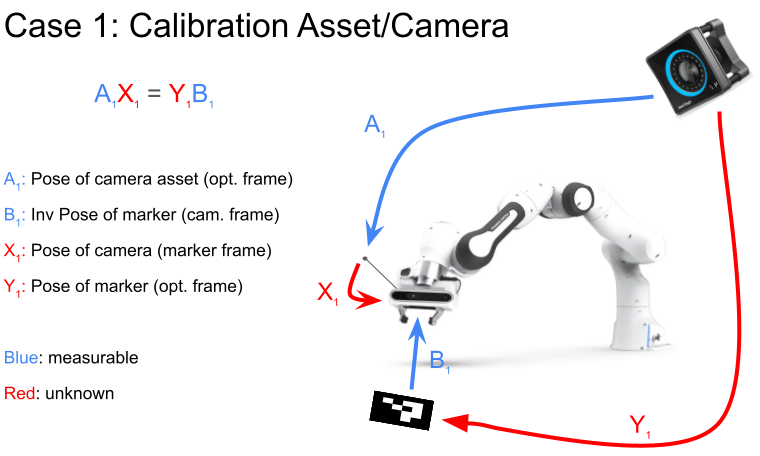
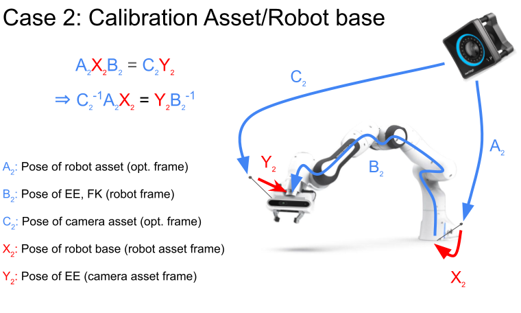
This repository presents a comprehensive solution to the hand-eye calibration problem, a fundamental challenge in robotics and computer vision. Hand-eye calibration is critical for applications requiring precise alignment between the coordinate system of a robotic manipulator (the 'hand') and a vision system (the 'eye').
Steps to install your project:
-
Clone the Repository:
git clone https://github.com/epfl-lasa/hand_eye_calibration.git
-
Build and start docker image:
cd hand_eye_calibration/docker bash build.sh bash start.sh -
Compile the project:
Since the src folders are imported as a volume in docker for now, do not forget to build the project
catkin_make
-
Camera:
If you are using a realsense camera you can just start a node using the given bash file
bash src/scripts/camera.sh
-
Marker detection:
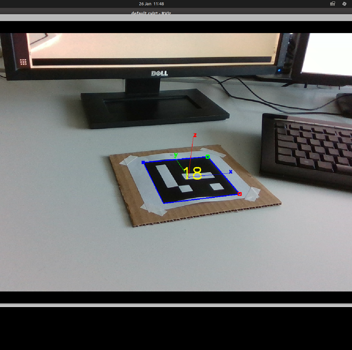
Verify that the topic names in /src/aruco_ros/aruco_ros/launch/single.launch corresponds to the topics the camera is publishing and run the marker detection with the following script
Link for markers: https://chev.me/arucogen/
In the following bash script change the markerId and markerSize corresponding to you print:
bash src/scripts/marker.sh
-
Optitrack:
Refer to [https://github.com/epfl-lasa/optitrack_ros_interface] to publish the pose of your camera and change the topic name in src/scripts/record.py accordingly
-
Data recording:
In order to record the data with a franka panda you can use the branch "calibration" of the repo: [https://github.com/epfl-lasa/panda-task-control/tree/calibration] to move the robotic arm to different poses and to send the data to the recording process. First start the following script to recording the data and save it correctly:
python3 src/scripts/record.py
Once the data of a pose has been recorded the calibration script will move to the next position. Mathematicaly a minimum of 3 pose are required, by default nt = 53 (5 for each axis) an nr = 2 (two Z axis rotation per position), the pose are then saved as .npy files
-
Data processing:
python3 src/scripts/process.py
The matrices X1, Y1, X2, Y2 are saved as .npy file
An error metric will be printed, here you have some comparison values for a good calibration previously done:
| Error Type | Case 1 Values | Case 2 Values | |------------|---------------|---------------| | Total Error | 0.0013 | 0.0012 | | Rotation Error X | 0.432 deg | 0.165 deg | | Rotation Error Y | 0.336 deg | 0.376 deg | | Rotation Error Z | 0.499 deg | 0.504 deg | | Translation Error X | 2.54 mm | 3.48 mm | | Translation Error Y | 0.88 mm | 3.96 mm | | Translation Error Z | 2.58 mm | 5.85 mm | -
Calibration testing:
It's important to understand that a small error does not automatically imply a successful calibration. It merely indicates that, based on the provided sets of Ai and Bi, the estimated Xi and Yi are sufficiently accurate. The calibration's quality also depends significantly on the variation in the poses. To evaluate your calibration quality in the first scenario, execute the script provided below. This script publishes a PoseStamped message detailing the error in the Object Frame (B1 X1-1 A1-1 Y1).
python3 src/scripts/test.py
Reposition the robot arm into its extreme poses, ensuring the marker remains within the camera's field of view (without moving the marker). This is to verify that the published error remains minimal for poses beyond the calibrated volume's boundaries.


