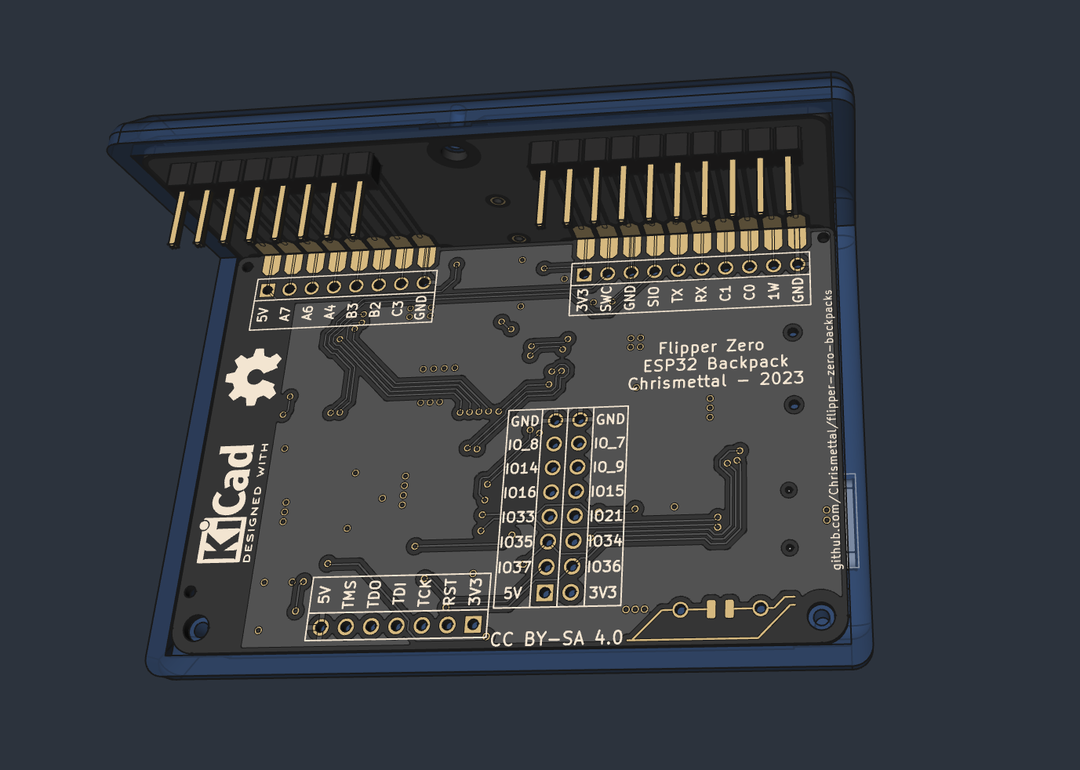
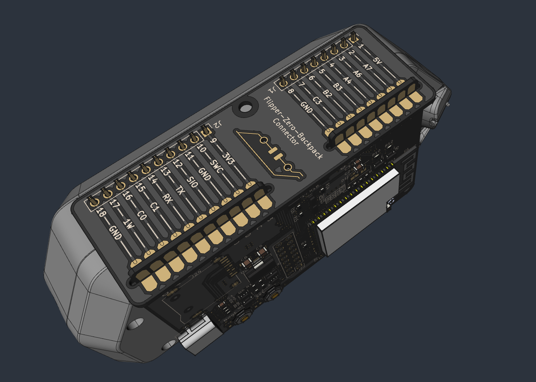
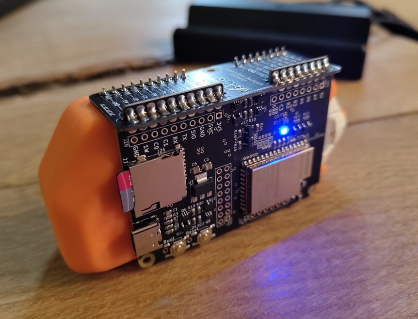
This is a collection of addon boards for the Flipper Zero multi-tool in the style of a backpack that clips behind the Flipper!
Right now it features only an ESP32 wifi board, like the official wifi devboard, only formatted as a backpack and with an SD card slot fitted. There is also a protoboard to create your own designs in the same formfactor.
The backpack framework is designed to fit snugly to a Flipper inside its silicone case. Without a silicone sleeve, the board will have 2mm of space around the Flipper, which might be undesireable.
Finished designs are currently stocked at Tindie.
If you like my work please consider supporting my caffeine addiction!
All boards use 1mm board thickness unless otherwise specified.
Every board uses the same connector up top. This is what plugs into the Flipper and makes the board an actual backpack. The addon board and the connecting piece slide into each other and get soldered at the intersection to form a solid, right angle connection.
Very similar to the official Wifi dev board. Additionally includes a micro SD card slot so you don't have to mod the official board yourself.
Other than that all guides applicable to the official Wifi dev board are also applicable here.
The board ships with the Black Magic debugger firmware, just like the official board. Alternatively you can use an alternate firmware like the ESP32 Marauder by JustCallMeKoko if you want to get spicy.
Every firmware that works on the official dev board should also work on this backpack
The ESP32-S2 part number referenced in the BOM (C701334) leads to an -I version of the ESP32-S2, which has the antenna plug mounted on the ESP. Versions without the -I in the product name do not have the antenna plug mounted. Next to the antenna plug is a small jumper that is set accordingly, to use either the internal PCB antenna, or the external plug antenna.
By default, -I ESPs have the jumper set to use an external antenna via the plug.
If you use a non -I variant of the ESP32-S2, like the boards found in the shop, you would have to mount an antenna plug before being able to use the external antenna
if you use an -I ESP32-S2 you would need to move the jumper over to use the internal antenna!
kThe ESP seems to be pretty restrictive in SD Card compatibility especially when running Marauder. This is not a limitation of this specific design but inherent to the ESP32. I've had luck with older and smaller SD cards sub 16 GB and Class 10 at max. OLDER Sandisk Ultra Micro SDHC I seem to work pretty well when formatted to FAT32.
A simple 2.54mm pitch protoboard backpack, fitting the same case as the ESP32 board. While it is through hole, beware that there isn't much space between the Flippers silicone case and the board, so make sure to only put taller components on the side facing away from the flipper, and stay pretty flat when wiring on the bottom side. Also remember that the bottom side will be somewhat exposed, so you should consider placing and wiring mostly on the encased side.
(Better image to follow once boards arrive)
This is an adapter to supply and connect a Raspberry Pi Zero W to the Flipper via UART.
The board was mainly created for the Flippagotchi app, which renders a Pwnagotchi`s screen onto the flipper.
Additionally, the board includes a PCF8523 realtime clock so your Pwnagotchi actually knows what time it is. The battery used for the RTC is a CR927.
The soldering guide can be found on the PCB itself. You will need a Raspberry Pi Zero W WITHOUT ANY PIN HEADERS MOUNTED, which will be layed flat onto the adapter PCB before being screwed down. The required pin headers will then just be filled with solder.
TODO: Doc on how to set time follows when the boards arrive
All files to order your own boards from existing designs can be found under /pcb/<BoardName>/FabricationFiles. This includes Gerbers as well as BOMs for PCBA so the boards arrive fully built. All files were exported to be ordered at JLCPCB and use LCSC part numbers.
All boards need to be ordered as 1mm thickness so they fit together well!
There is also a clean KiCad project under /pcb/Clean/ to create original designs. If you end up creating your own design I would love to merge your fork into this repo!
A 3D printable case project is included in /3d_printing/flipper-zero-backpacks.FCStd.
You can use FreeCAD to open and modify it.
A bare version, as well as one fitting the ESP32 board have been exported as .step and .3mf files into /3d_printing/.
The cases can be printed without any supports and are best printed in PETG, but there is no reason why PLA wouldn't be sufficient.
Detailed build guide - click to expand
Step 1 - Clamp the back board vertically
Step 2 - Slide on the connecting piece
Step 3 - Solder down one of the connectors
You don't have to care about the angle of the boards for now.
Step 4 - Reflow the connection, aligning the boards at 90 degrees
Step 5 - Make sure the boards are also aligned when viewed from the front
Step 6 - Solder the remaining connections on the top
Step 7 - Make sure that none of the connections are bridged between the pads horizontally
Step 8 - Flip the board around so you can see the bottom connections
Step 9 - Solder the bottom connections
Step 10 - Flip the board around again and solder the pin headers
Make sure to get them at a right angle to the board as well. Otherwise you will put stress on the board when inserting into the Flipper.
Step 11 - Optional - Find the 3D printed case and screws
Step 12 - Slide the board into the case and screw down the 3 mounting points
If you like my work please consider supporting my caffeine addiction!
This work is licensed under a Creative Commons Attribution-ShareAlike 4.0 International License.


