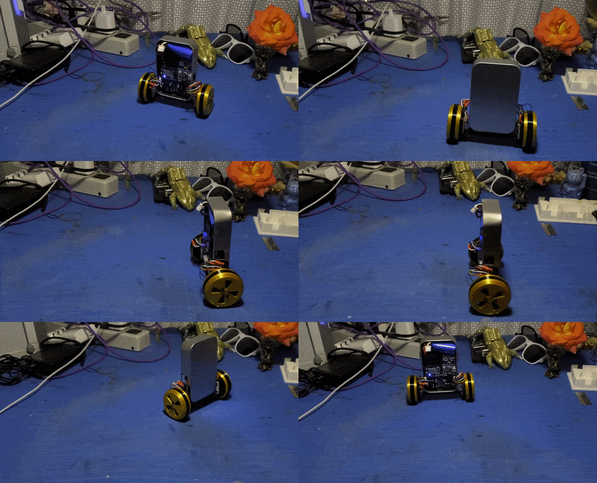
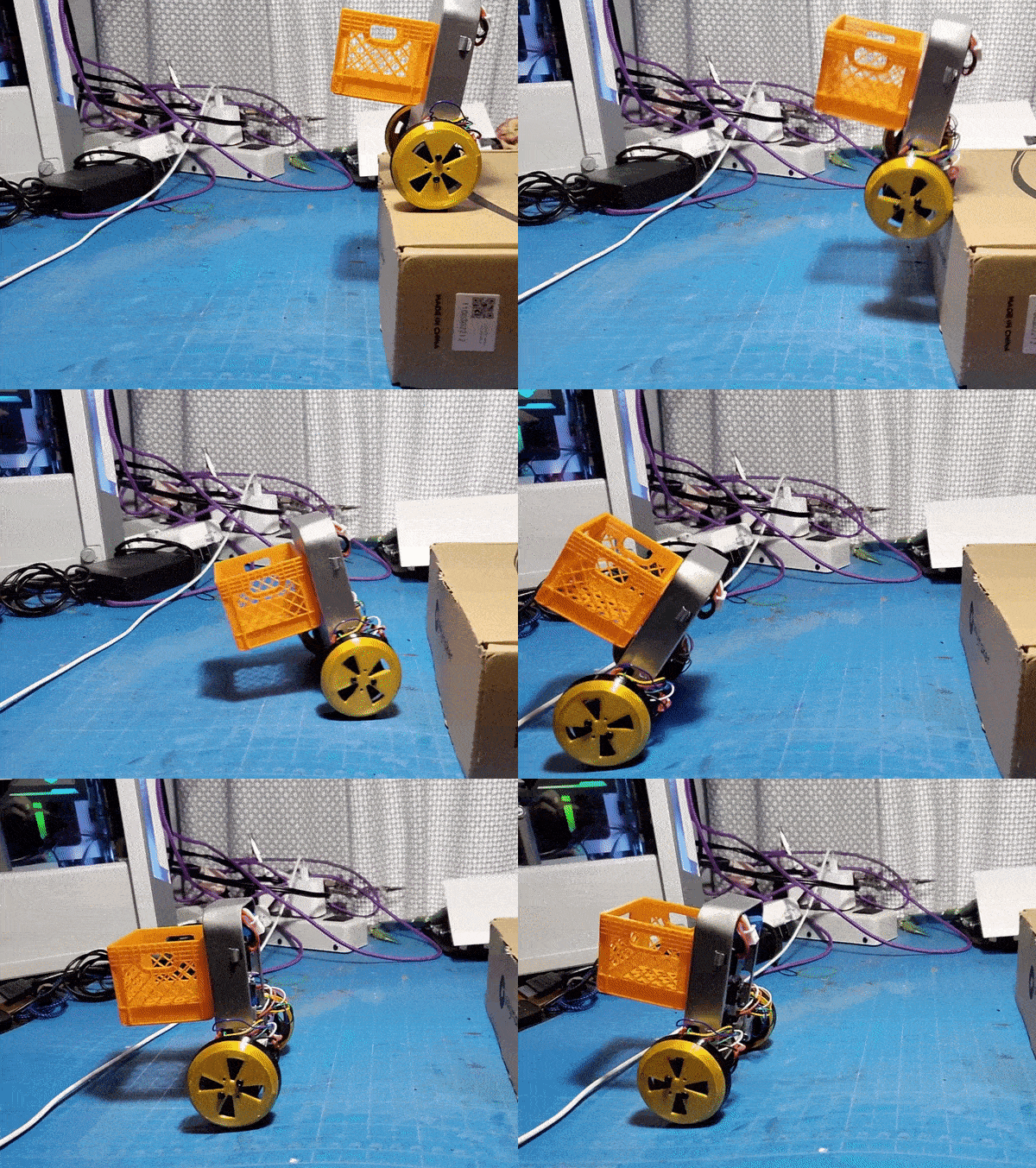
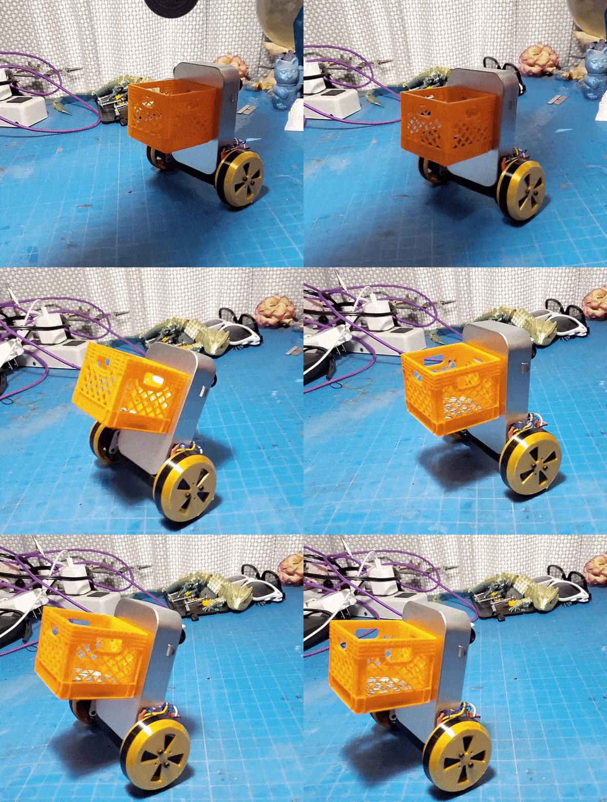
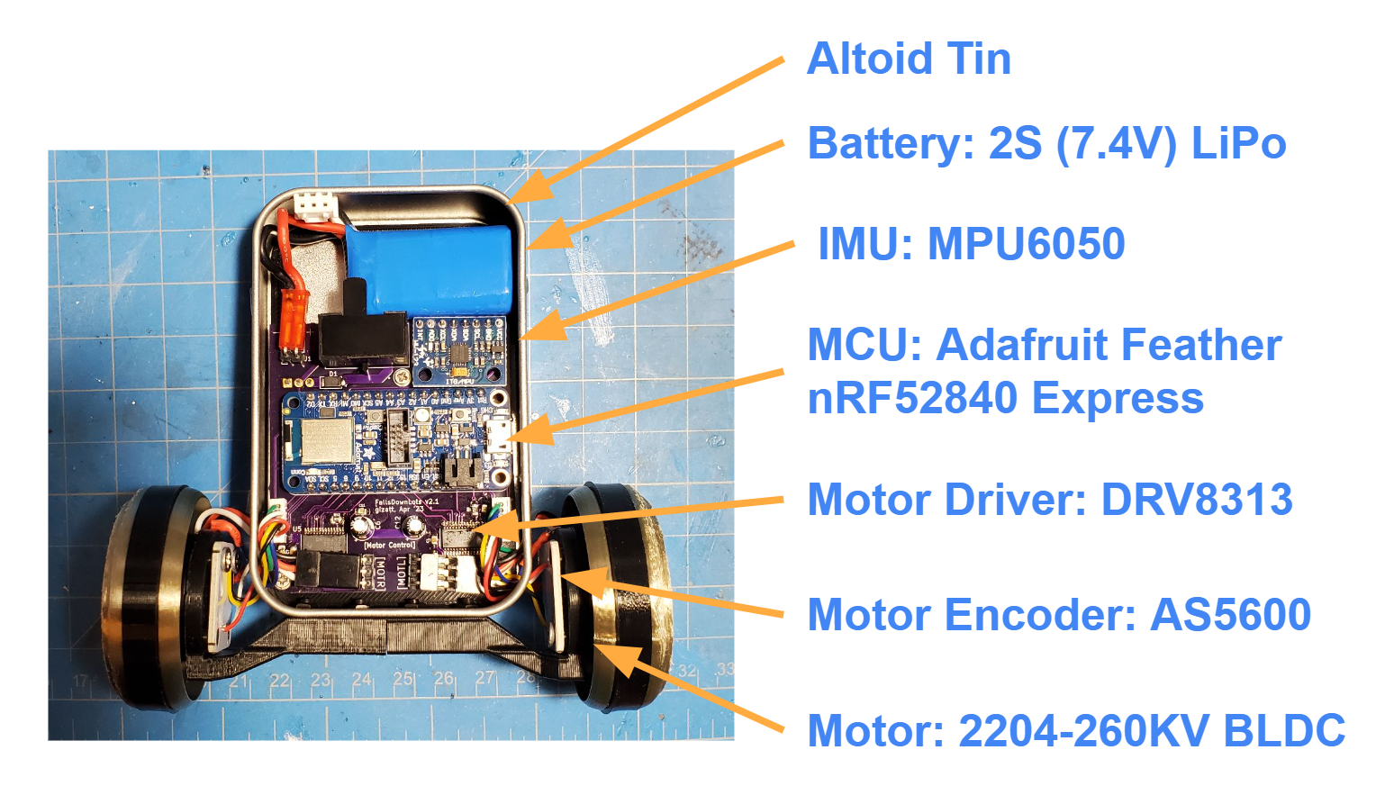
This project ("FallsDownLots") is a 2-wheeled balancing robot designed around two brushless DC (BLDC) gimbal motors, controlled with field-oriented control. Previous iterations of wheeled balancing robots I've built have been plagued by issues with poor motor control (primarily backlash, inertia, and friction causing shaky control around the upright fixed point). This project instead uses a high-torque (specifically low KV / high winding count) 3-phase motor, paired with an absolute magnetic encoder to determine the shaft angle, and a 3-phase drive circuit to deliver current. With some pretty simple parts, I've been able to get something pretty close to actual torque control for the wheels of this robot, and it's been pretty easy to tune up for smooth, stable, remote-controllable operation.
For ease of control tuning, I chose a main board with Bluetooth Low-Energy (BLE) support, and written a companion program that connects to the robot and allows parameter updates. This program is currently very primitive but it beats reprogramming or having it drag around a serial cable (which interferes with control).
I mostly rely on SimpleFOC for the actual FOC implementation, and took their advice on sensor and drive chip choice. I'd like to dive deeper into controlling these motors better -- for example, trying to compensate for cogging torque to get smoother operation - but I have more fundamental issues to fix first (see below).
- For code, see the
fallsdownlotssubdirectory (which is a PlatformIO package). - For CAD, see Onshape. Sorry it's not organized into a main assembly yet, this is just my 3D print part workshop. Approximately up-to-date STLS are in the
stlssubdirectory. PrintMotorMounttwice, mirroring one of them. PrintWheeltwice. PrintTiretwice in TPU or another tacky, flexible filament. - For PCB design and electrical schematics, see
board_v2subdirectory (which is a KiCad project).
(Note: this references a special-edition physically packaged version of this robot.)
Parts list:
- 2X PLA wheel with TPU tire
- 2x Motor assembly, composed of...
- 1x PLA Wheel + TPU tire
- 1x PLA Motor Mount
- 1x AS5600 Breakout Board
- 1X 2204-260KV BLDC Motor (with 3-pin JST RE connector)
- 1X 10KOhm Thermistor
- 1X JST MX 6-pin Male Connector
- 1x Altoid tin case with lid, containing...
- 1x PLA board mounting backplate, already attached to case.
- 1x Main electronics board
- 4x M3x8mm hex bolts and nuts
- 8x M2x4mm hex bolts
- 3x M2x8mm self-tapping phillips screws
- Spare parts: M3x8mm self-tapping phillips screws, plus other screw types, plus spare TPU tire
Not included (supply seperately):
- 1x 400Mah 2S LiPO [Amazon link] and balance charger.
- 1.5 and 2.5 metric alley keys
- Small phillips head screwdriver
- Small narrow / needle-nose pliers
- Non-ancient bluetooth adapter (probably needs BLE >= 5.1?)
Assembly is simple, but the tight packaging makes assembly pretty order-sensitive.
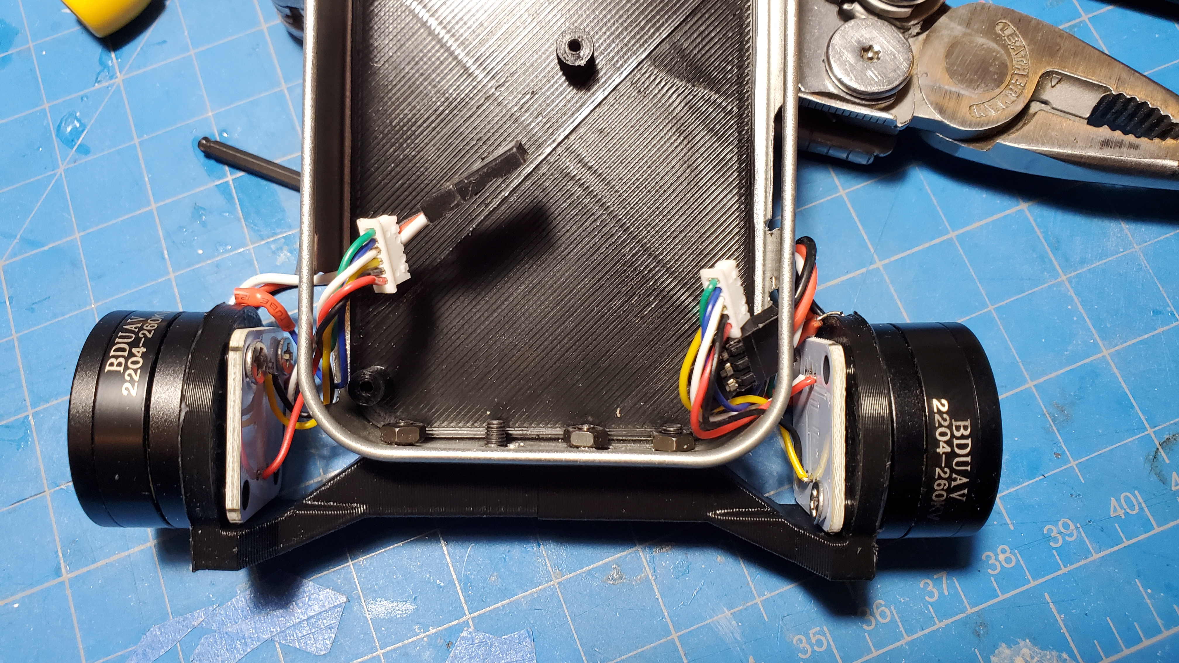
- Attach the motor assemblies onto the bottom of the case, as shown, using 4x M3x8mm hex bolts and nuts. Before you fully attach these, pass their wires into the case through the nearby holes; otherwise it'll be a tight fit to get those wires passed in, especially with the electronics board mounted. Be reasonably gentle with the wires...
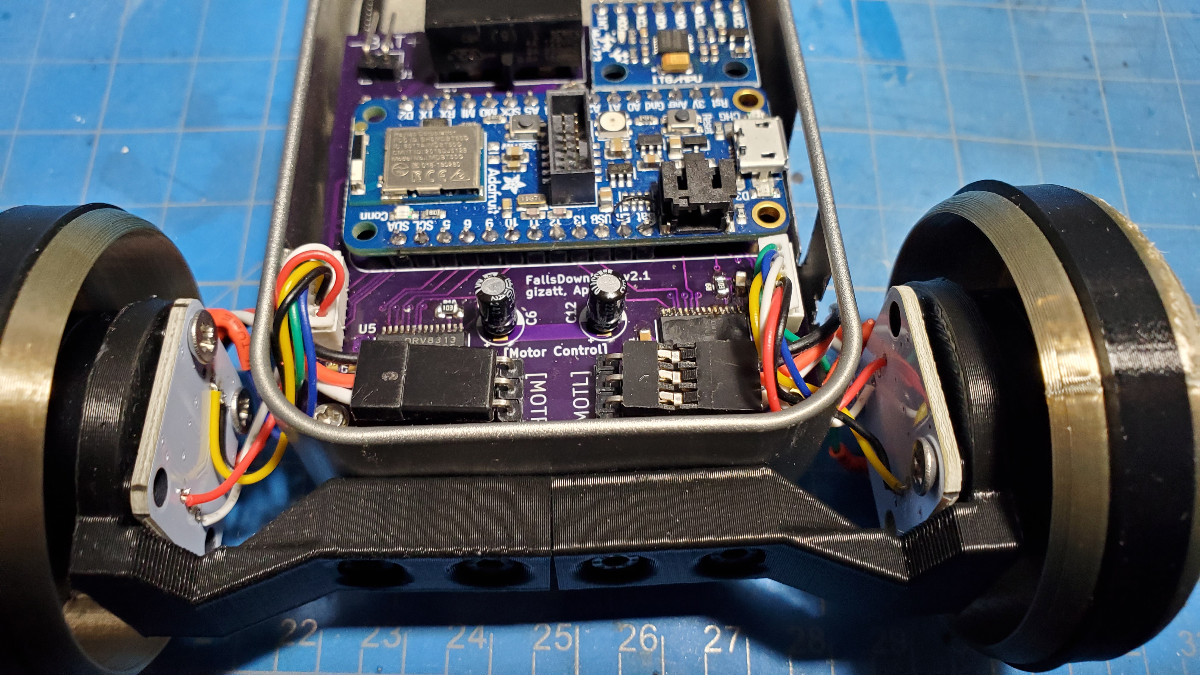
- Now install the main electronics board by sliding it into place and installing the 3x M2x8mm self-tapping phillips screws, which screw into posts on the PLA backplate. Note that you want the wires from the motor assemblies over the main board once it's installed -- it's a bit of dance to get it everything into place.
- Plug in the wires from the motor assemblies into the plugs on their corresponding side. See picture for exact orientation of wires -- carefully note the orientation of the 3-pin motor connectors! If you get this backwards, the motors will spin the wrong way. I recommend some good needlenose pliers to help with wrangling and attaching these cables.
Troubleshooting: contact me!
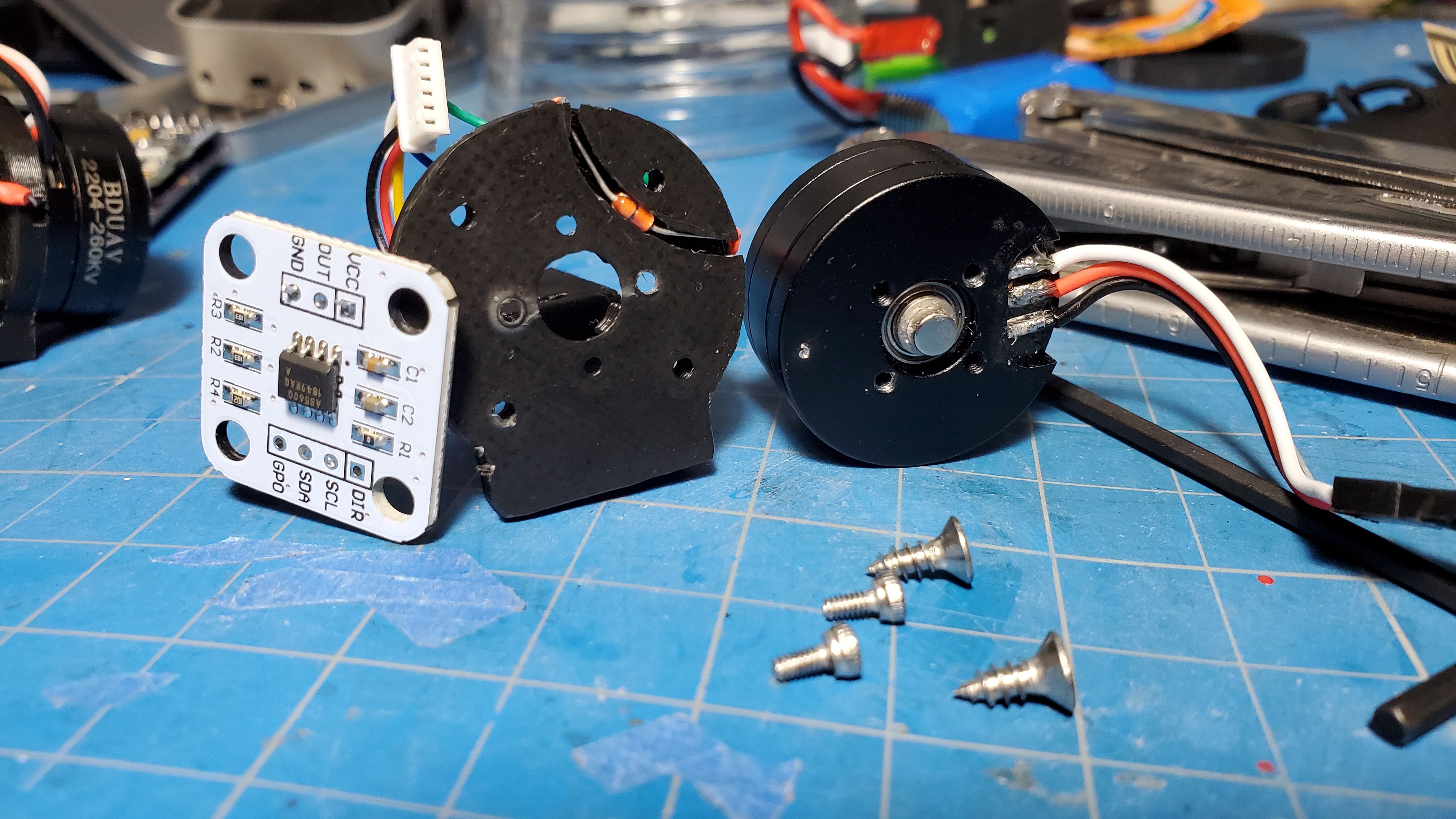
I packaged this robot with each motor and sensor already assembled, since their assembly is a bit sensitive, but you're welcome to disassemble and take a look. These assemblies are pancakes of a tiny BLDC motor (Amazon link, though this unit is much cheaper on Aliexpress) with a magnet superglued to its shaft, an absolute magnetic encoder on a breakout board, and a thermistor sandwiched between them.
Flip the switch to the right to turn on. I recommend laying the robot down or standing it on its head during startup; each wheel will independent move a quarter rotation back and forth during startup as a calibration routine (this is managed by SimpleFOC). Once that is done, the robot should be active, and will attempt to balance to the upright if it is within ~60 degrees of upright. The easiest way to get it going is to go to a clear area of floor, holding it sideways, and confidentally and quickly place it roughly upright and let go. The integrators reset and motors turn off again when it is not upright, e.g. if it falls.
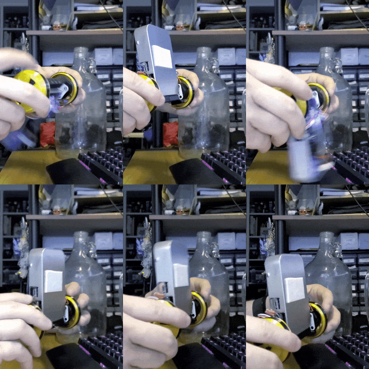
I recently discovered another fun demo method that happens to work, despite the control algorithm not being created with this in mind: hold the robot by the wheels, and swing the robot upright. It should catch itself at the upright and stabilize there. See this video.
Note: there's a few bugs somewhere in the code, especially in the BLE stuff, and sometimes the IMU or magnetic encoders get into weird states and stop talking. If the robot suddenly stops and falls over, or otherwise seems unresponsive, just do a complete power cycle. This is more likely to happen if you're using one of the BLE scripts, proportional to how much data you're sending/receiving.
The main control code is implemented in main-fallsdownlots.cpp::do_control. I'm currently running a PID loop on angle, with the zero angle estimated via a low-pass filter on the measured angle (which assumes we stabilize on average to the upright), plus a PI loop on wheel velocity, plus a PI loop on yaw velocity. These are all controlled by parameters in the ControlParams struct.
There are two Python scripts in the fallsdownlots/scripts folder. Both connect to the robot with BLE.
communicator.py: Once connected, type a command of the format " " and hit enter, and it'll send it to the robot. It should echo the new setting back, though sometimes it takes a while to come back. If you just send "" without a value, it'll send the current value back. Example: "ANG_D 0.1" changes the derivative gain to 0.1. Ignore the plot window that opens up, it doesn't work yet...gamepad.py: Connects to the robot and sends commands (adjusting the setpoints of the velocity and yaw velocity control loops) in response to the arrow keys, letting you control the robot. Hold shift while pressing arrow keys to go faster. There's a mode to display robot odometry (see code) but it's currently super sketchy.
- Major code cleanup. Tons of cruft left here I haven't re-orged.
- Use BLE interface to create an interactive motor teststand for tuning up actual motor control loops.
- Because I'm talking to 2 magnetic encoders and 1 IMU over relatively slow I2C (800khz, I think), I haven't been able to get my main control loop to run faster than ~200hz. I'm configuring the IMU to do its own high-rate on-board orientation estimation, so that's fine -- but this low rate makes it hard to drive the motors in anything other than torque mode (velocity and position mode go unstable pretty easily / can't be tuned to be too accurate as my loop rate is probably too low), and I can't crank the actual control gains as high as I'd like for tight tracking without inducing oscillations. It's possible I can get info from at least the magnetic encoders over their analog output instead... but I would need to experiment with that.
- I'm relying on Bluetooth Low-Energy as my wireless comms media, but I'm finding the bandwidth super low, and the code on the embedded side super crash-prone. I'm probably overloading buffers somewhere and configuring stuff wrong... next time, I'm just gonna have the robot connect to my Wifi. I'd rather deal with networking gremlins I sort of understand than BLE ones I don't.
The robot sends a 36-byte (+COBS-encoding) packet over BLE UART at ~30hz consisting of 8 floats:
[pitch, yaw, d_pitch, d_yaw, odometry, l_cmd, r_cmd, max_motor_temp]
On-board, the robot has a registry of named control parameters that you can write with a command formatted:
<NULL-TERMINATED-NAME>[optional single float]
and the robot will respond with a similarly formatted message (+COBS-encoding) packet with a single float indicating the updated value, or the current value if you didn't include the float value.
