This is a upload of the current status of the CadCam program. Not finished, only for info to other parties.
The Cad Cam program has a opengl interface. This upload is specific for testing pocket offsets, CavalierContours https://github.com/jbuckmccready/CavalierContours
Cavaliercontours works with lines (primitives) with a bulge factor 0. The line has become a arc if the bulge factor is !=0. A bulge factor of 1 is half circle. (semicircle). The bulge factor <0 is a g2 or cw arc. The bulge factor >0 is a g3 or ccw arc. The Cadcam program accepts bulge factors bigger then 1 and preprocess them for the cavaliercontours data input.
If the cadcam program has to input a spline into cavaliercontours the following method is used:
- Convert the spline to points (linestrip), the output resolution can be 0.000001 to 1. (time)
- Avoid nested points, the points are exepted when distance is bigger than value l. l=lenght value for accepting output. *cavaliercontours is not accepting nested items, wich is normal.
- Store the points in a simple xyz data container of type : std::vector and pass them into the cavaliercontours with bulge factor 0, as linestrip.
- A charming solution can be to pass in bulge value's. This can be adapted quite easy into the source code.
The program has no QT dependencies. It's important to use the std library and leave the QT libraries untouched. In this way the program can be ported to other platforms in minutes.
The program can load dxf files from : -librecad, use only the spline trough points. -freecad. -inkscape, used for trace bitmap, objects to path.
The program has a contour recognize button (process) to reorganize the dxf drawing into closed contour path's.
- Red is a cw path.
- Yellow is a ccw path.
- Grey is open path. The contour recognize class is a powerfull one that can handle huge ammounts of dxf data. More then sheetcam or dxf2gcode. The offset parameter is - for inside and + for outside offset.
The order of contours is done by the depth sequence. Depth 0 is the contour without inner objects. Depth 1 is a inside contour of Depth 0, and so on. There is no limit to the depth sequence. The cnc cut sequence is perfect ordered in this way.
The gcode output is done for the orginal cad contour. Later it can be expanded to process specific cad layers, contours, depth's, etc.
Think about adding post processor files etc.
Another great 15 minute invention is the true spline primitive. This is a natural cubic spline algoritme that has a unique property. The spline has no difference if drawed from left to right or visa versa. Therefore it's great to implement in cnc machinery, stock market prediction, robot backwards interpolation etc. The spline can be swapped wihout noticing any changes in output.
Used spline algoritme : https://mathworld.wolfram.com/CubicSpline.html Expanded with : difference function
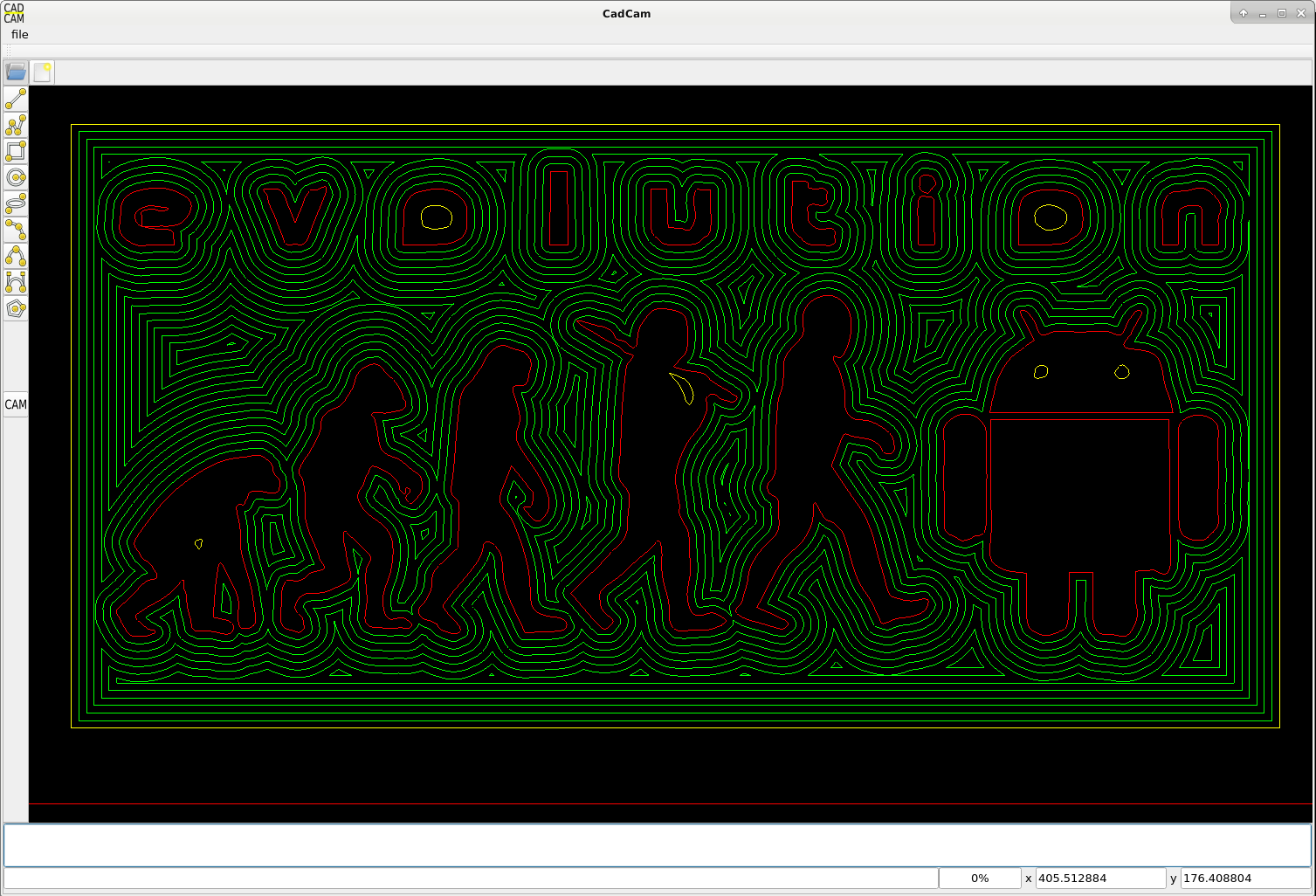
To make a succesfull pocket output : -open the file /drawings/evolution.dxf, process this file, try offset -1 and +1. -in the source code keep in mind if you got the depth==0, depth==1 correct. -consider to process the pockets before the depth sequence is done, if facing problems.
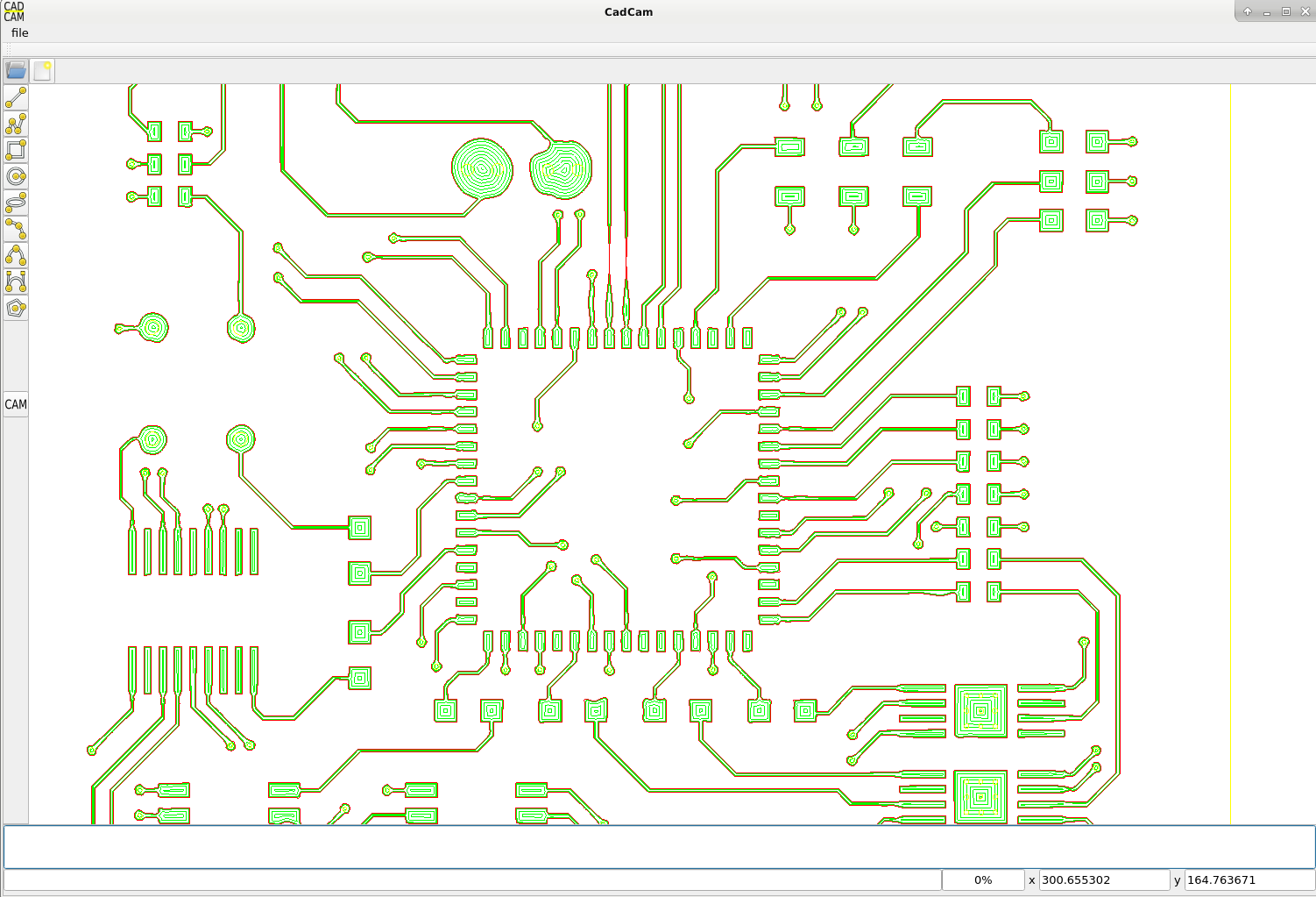
CadCam program output example wihout islands, see cam_offset.h :
 Example with islands, the islands are added in a loop, deactivate the comments cam_offset.h :