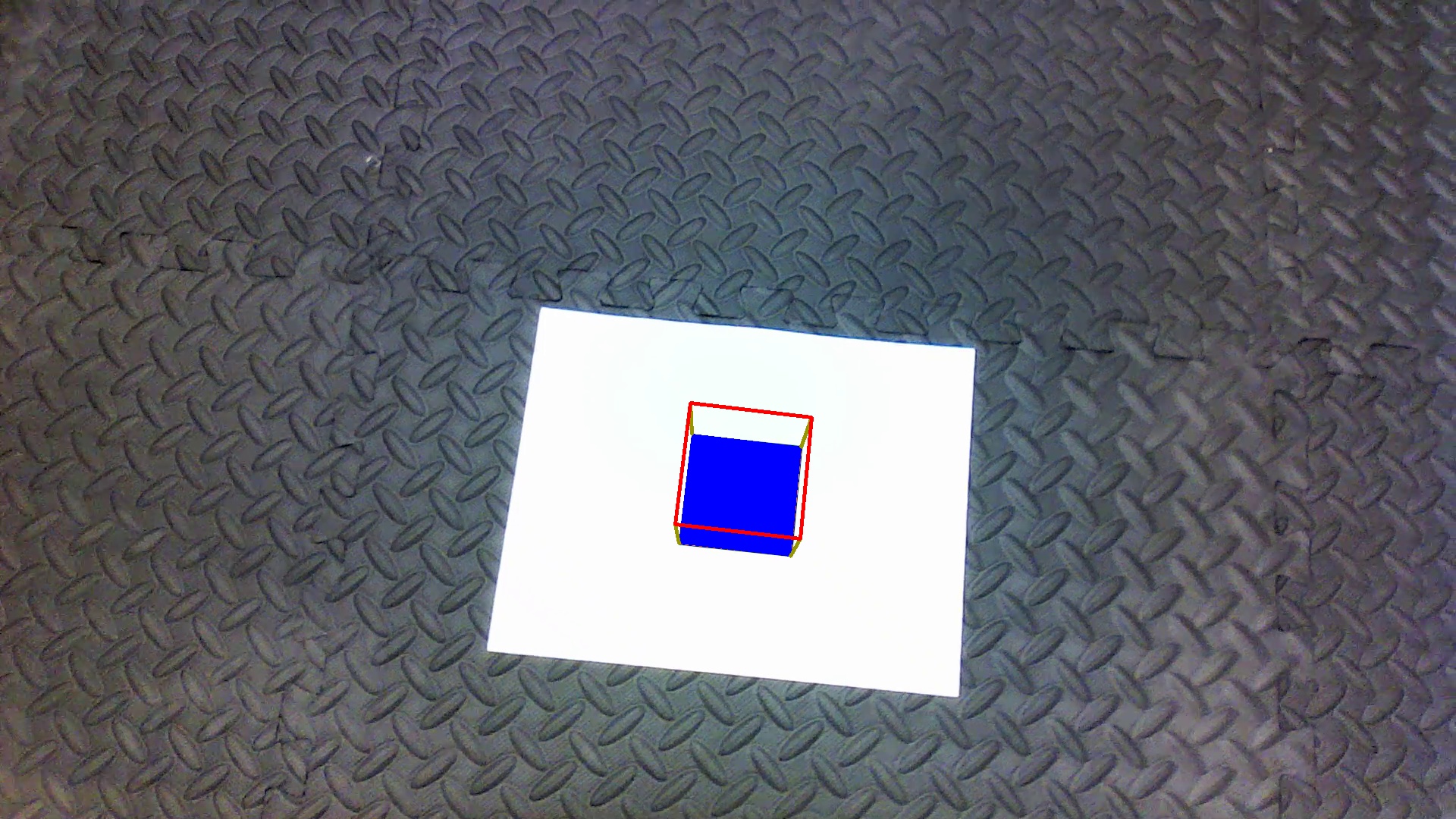
The project focuses on detecting a custom AR Tag (a form of fiducial marker), that is used for obtaining a point of reference in the real world, such as in augmented reality applications. The two aspects to using an AR Tag: detection and tracking, has been implemented in this project. Following are the 2 stages:
- Detection: Involves finding the AR Tag from a given image sequence
- Tracking: Involves keeping the tag in “view” throughout the sequence and performing image processing operations based on the tag’s orientation and position (a.k.a. the pose).
Prior to the implementation of image processing on the image sequence, the video is split into its image frames using cv2.VideoCapture, and once the operations are performed on each of the frames, it is appended into an array. This image array is then used to get the video back using cv2.VideoWriter
Following is the reference AR Tag that has to be detected and tracked:
AR Tags facilitate the appearance of virtual objects, games, and animations within the real world. The analysis of these tags can be done as followed.
- The tag has been decomposed into an 8*8 grid of squares, which includes a padding of 2 squares width along the borders. This allows easy detection of the tag when placed on white background.
- The inner 4*4 grid (i.e. after removing the padding) has the orientation depicted by a white square in the lower-right corner. This represents the upright position of the tag. This is different for each of the tags provided in the different image sequences.
- Lastly, the inner-most 2*2 grid (i.e. after removing the padding and the orientation grids) encodes the binary representation of the tag’s ID, which is ordered in the clockwise direction from least significant bit to most significant. So, the top-left square is the least significant bit, and the bottom-left square is the most significant bit.
Following are the AR Tags obtained on doing Perspective Transformation on image sequences.
The process of the edge and corner detection has been implemented in the following way:
- The video stream is first converted into image frames.
- Detection is performed on each of the frames and then taking the fps as 25, the video is formed again.
- In the code, the function
Edgedetecionhas been scripted which takes in the image, the old corners that can been computed and returns the new coordinates of the detected corners. This is repeated for each image frame. - The Computer Vision methods made use of in the above implementation are:
cv2.cvtColorcv2.medianBlurcv2.thresholdcv2.findContourscv2arcLengthcv2.approxPolyDPcv2.contourAreacv2.isContourConvex
- Once the Corners are successfully detected, the perspective transformation of the Tag is performed.
The function
perspective for taghas been scripted to get the transformed and resized tag image. The methods used for the transformation are:cv2.findHomographycv2.warpPerspectivecv2.resize
- After the above successful transformation the ID of the tag is obtained, the corners of the tag as well as its ID with respect to its original orientation i.e compensated for any camera rotation is obatined.
- The above process has been written in Python using several functionalities of Computer Vision such as Contours and Corner Detection algorithms.
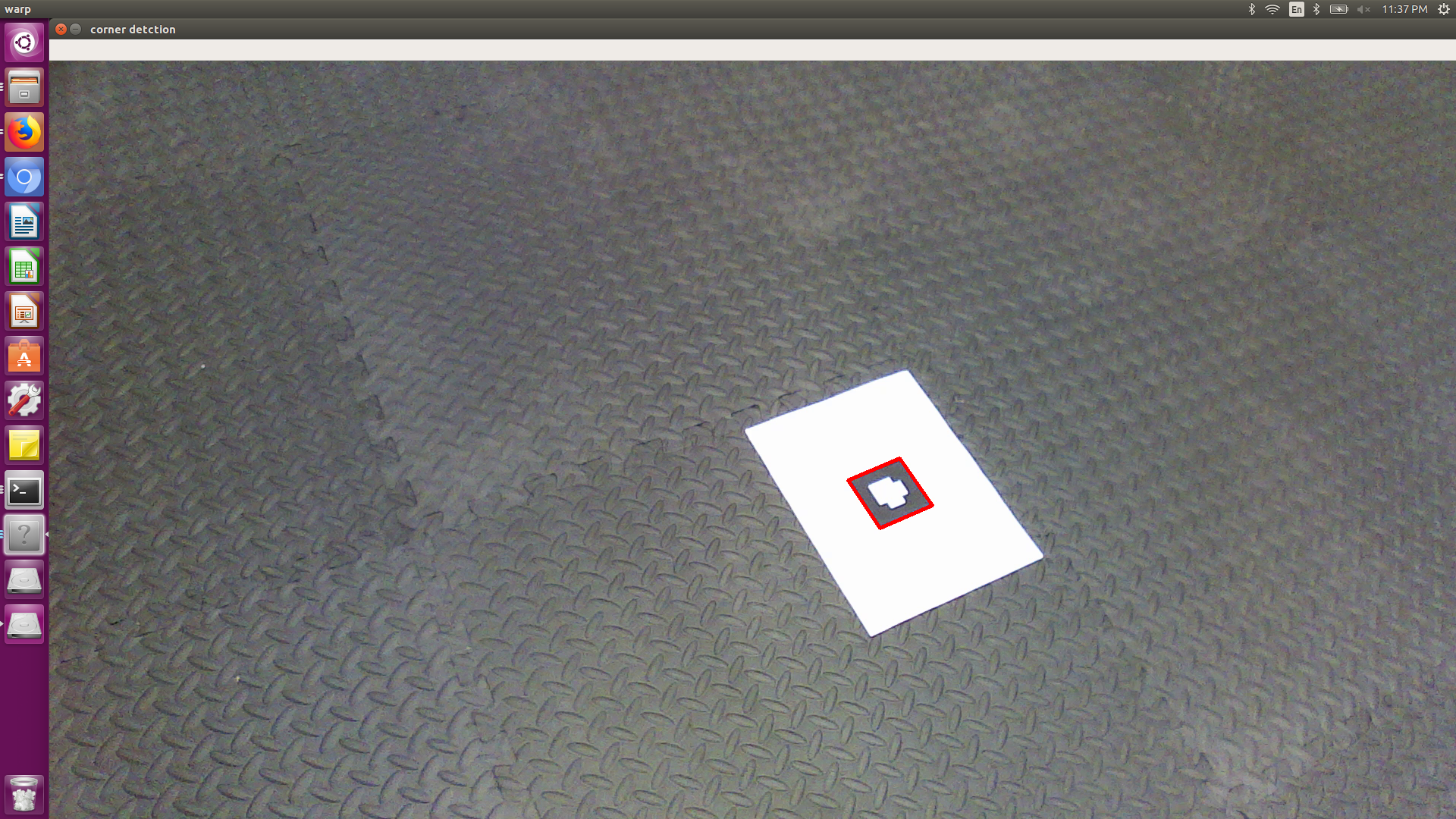
- Thus this part of the project successfully identifies and detects the AR tag in any given image sequence.
Screenshot of Tag Identification and Edge Detection Output
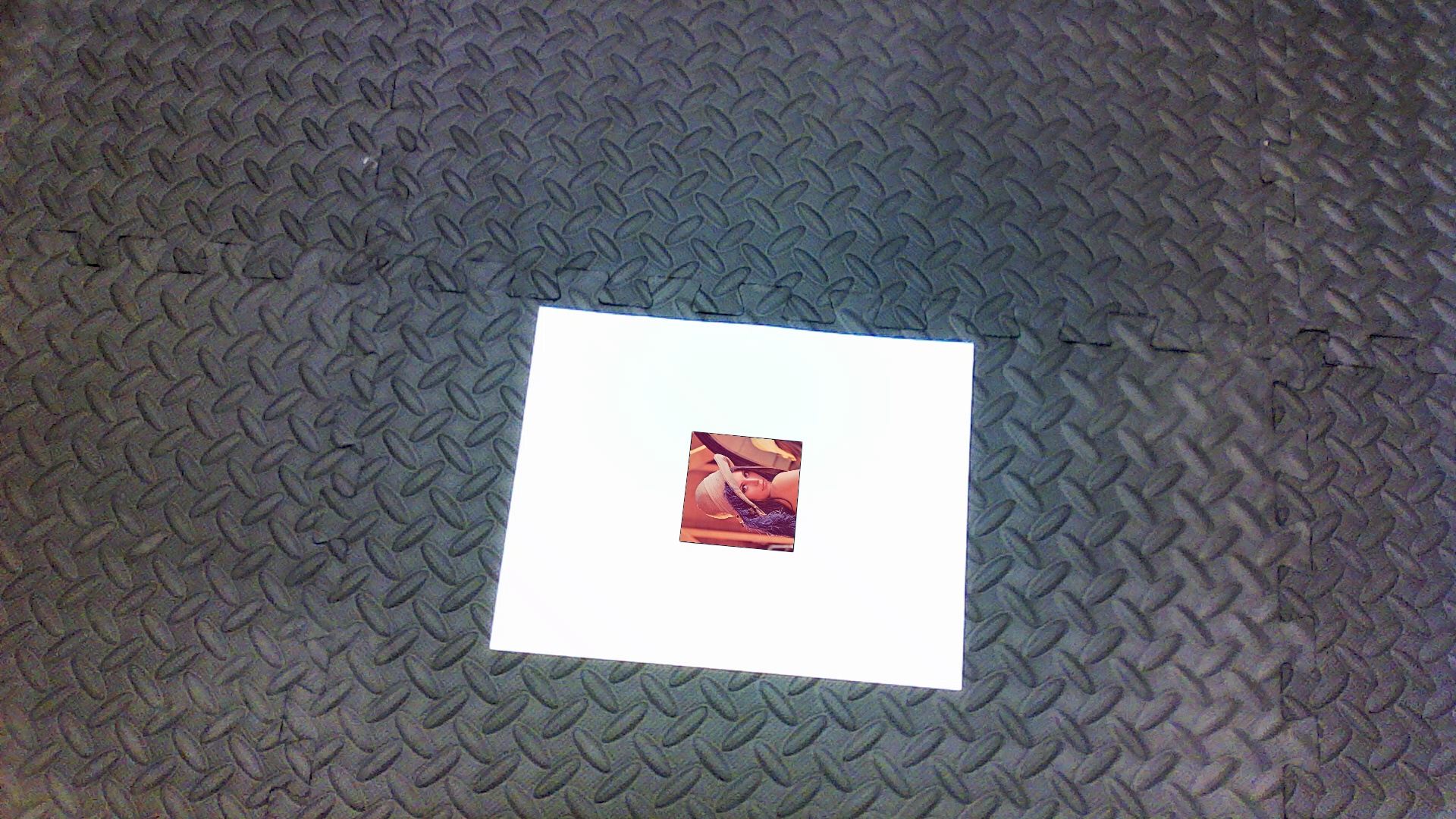
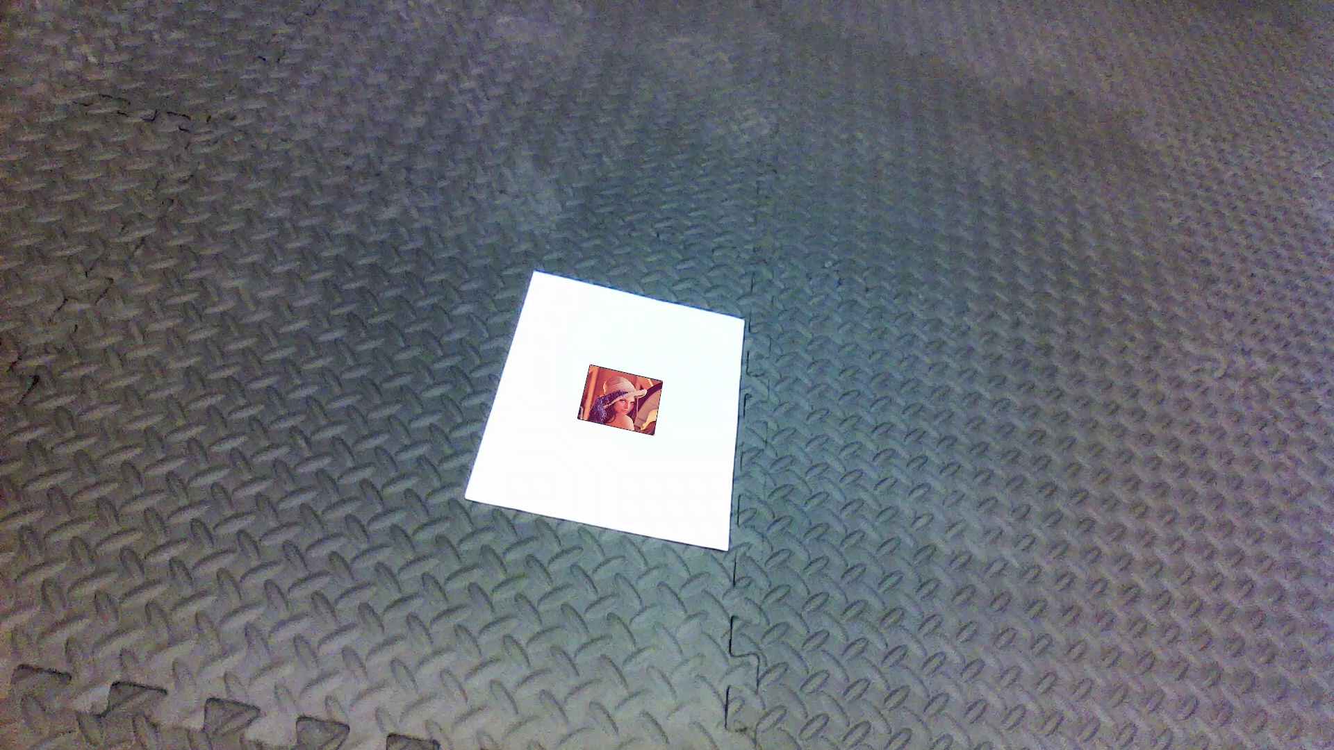
Homographic transformation is basically the transformation between two planes in projective space. In augmented reality, it is the transformation that projects a square marker board from the world coordinate system into a polygon in the image plane on the camera sensor (i.e., pixel coordinates). In this project, once the 4 corners of the tag is obtained with the Edge and corner detection done above, homography estimation is performed. This includes superimposing the image over the tag eg. the following image of lena.jpg
The following steps has been successfully implemented in this part of the project:
- Homography between the corners of the template and the four corners of the tag has been computed using the corners of the AR tag detected in the first part of the project. The homography matrix has been manually calculated in the code by finding the SVD of the world and camera coordinates system. The SVD function of the Linear Algebra library from the Numpy library has been used to calculate the same.
- Once the transformation of the template image has been sucessfully done above, tag has been done, the tag is “replaced” with the transformed image.
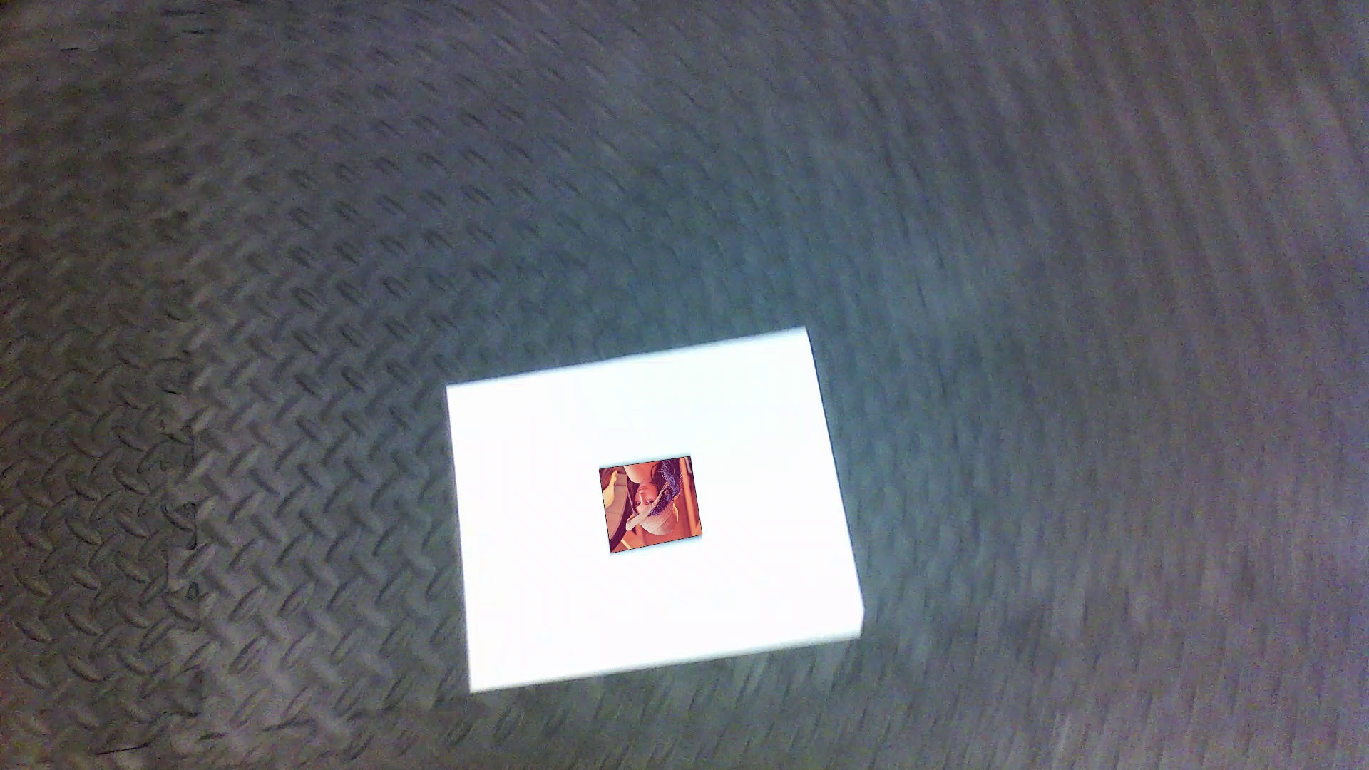
- This also implies that the orientation of the transformed template image must match that of the tag at any given frame, which has been taken care using efficient corner, contour and edge detection techniques to get the correct orientation of the AR tag at any given time.
- The above has been achieved using the calculated homography matrix to get the
cv2.warpPerspectivealong with the CV functioncv2.fillConvexPoly.
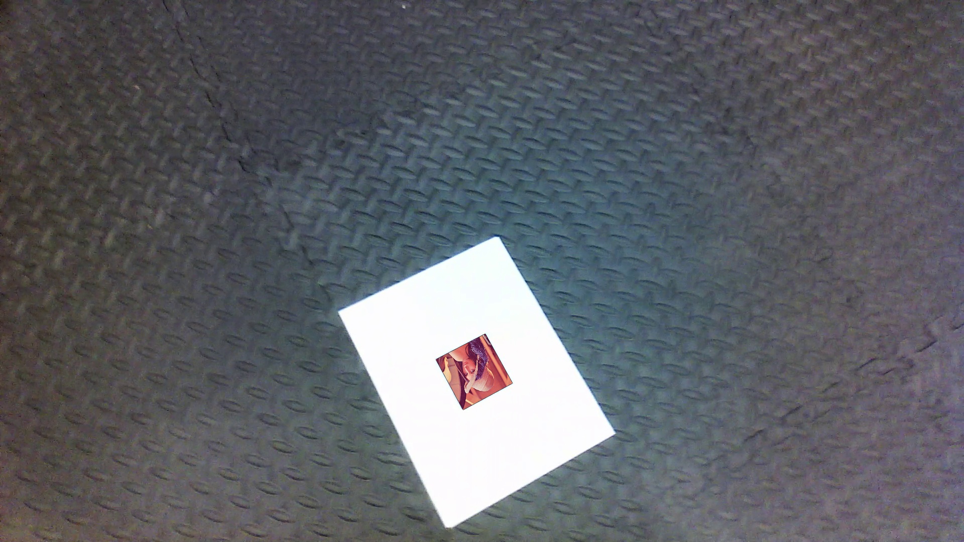
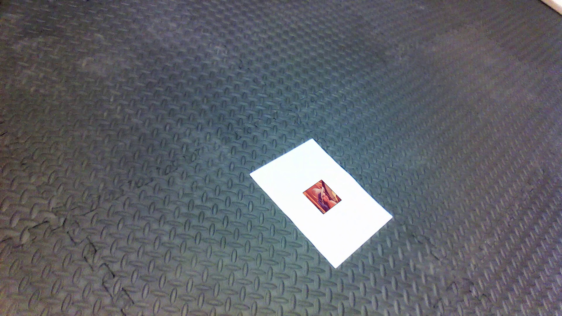
Following are the screenshots of the superimposed images of Lena.png on the AR Tag taken during the course of the video. The images show that the superimposed image maintains its orientation, thus compensating for the rotation of the camera.
Here the process of “projecting” a 3D shape onto a 2D image has been implemented.
- The homography between the world coordinates (the reference AR tag) and the image plane (the tag in the image sequence) is first computed. The calculation of this has been done by detecting the four corners of the marker in the input image captured by camera i.e the true corners for the UPRIGHT orientation of marker).
- The world coordinates of the corners is determined and the homography is computed between the detected corner points in the image (pixel coordinates) and the corresponding points in the reference (world) coordinate system.
- The projection matrix is then built from the given camera calibration matrix provided and the homog- raphy matrix. Here the camera’s pose i.e the rotation matrix R and translation vector t is found as shown in the code, and thus the projection matrix, P = K[R|t] is constructed.
- Assuming that the virtual cube is sitting on “top” of the marker, and that the Z axis is negative in the upwards direction, we have obtained the coordinates of the other four corners of the cube. This allows the transformation of all the corners of the cube onto the image plane using the projection matrix.
- The cube is then drawn using
cv2.drawContours
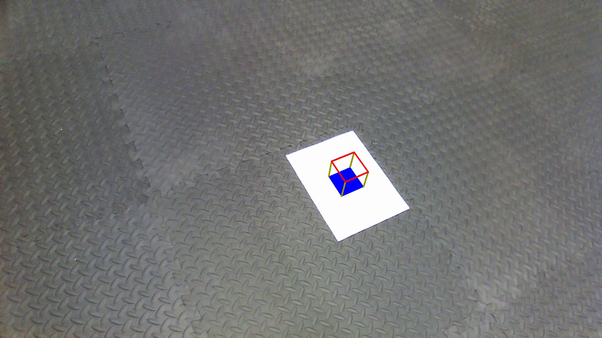
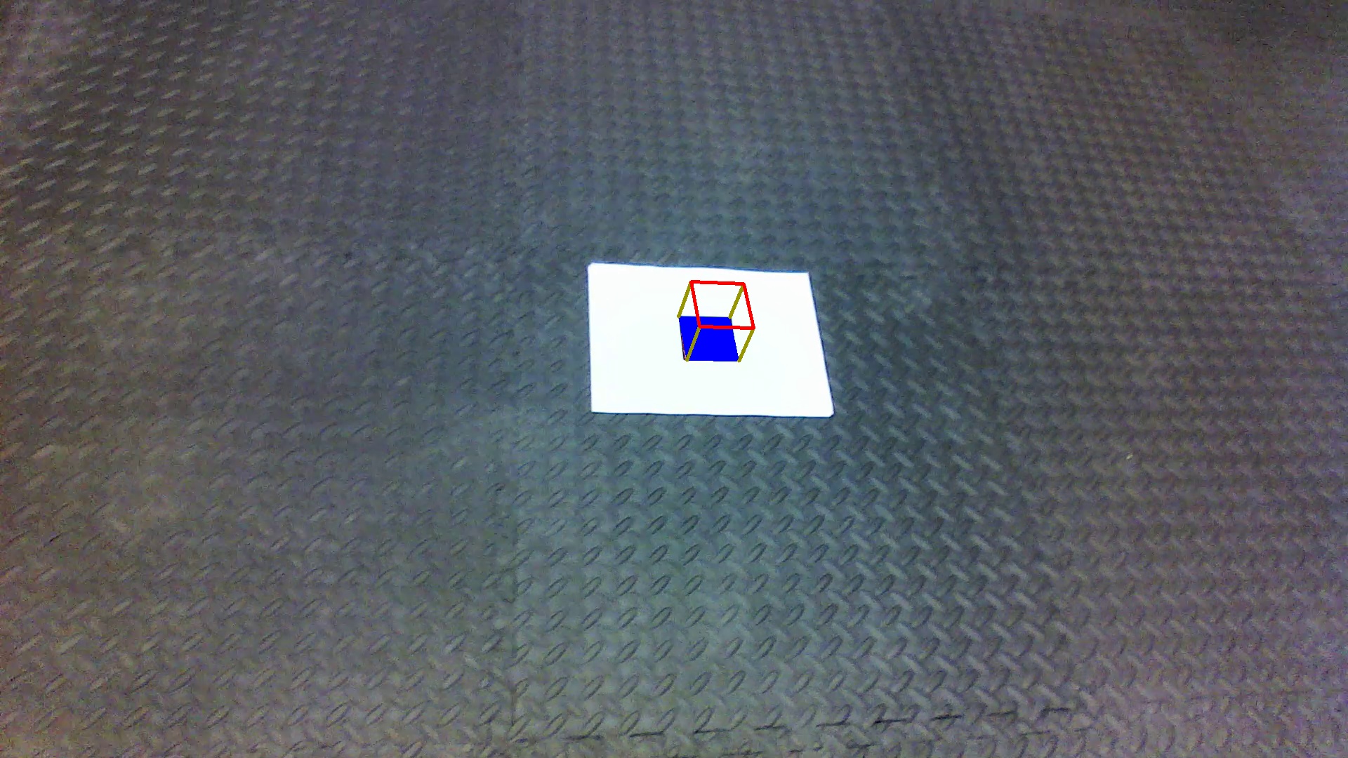
The implementation of all of the above steps has been clearly shown in the code. The following screenshot of video shows the Placement of the virtual 3D cube on the AR Tag.
Implementation of the concept of AR detection and tracking helped in the understanding of several concepts and a good knowledge of the challenges and appreciation of the maths behind digital images and cameras. The practical implementation of the transformation between the world and camera coordinates was exciting as we saw the beauty of linear algebra work. We understood the concept of homography in computer vision and the use of its libraries in python. The process of Edge and Corner Detection required several repeated optimization techniques to get the best result. This helped us understand the concept of Contours and various detection algorithms.
Koyal Bhartia(Koyal-Bhartia) - Graduate Student in University of Maryland with majors in Robotics. Interested in Computer Vision and Machine Learning of Autonomous robots
Harsh Kakashaniya(harshkakashaniya) - Graduate Student in University of Maryland with majors in Robotics. Interested in Medical, Mobile and Agriculture robotics.
