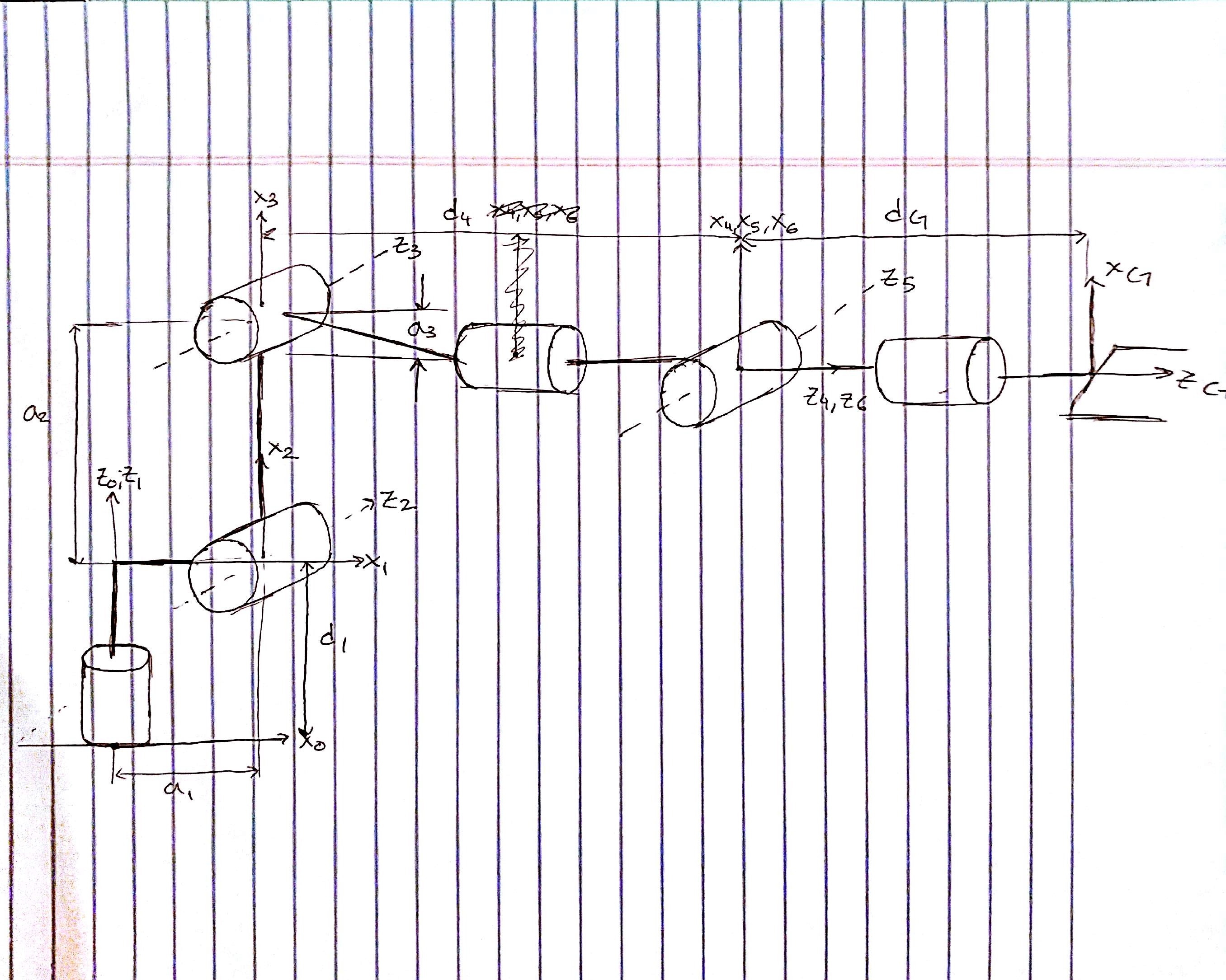
The DH Parameter table was created with a combination of the lessons provided and manual testing. Using the DH paramater table derived in lesson P-12 as a starting point, I used a Jupyter notebook to verify and check all my DH paramaters. The notebook can be viewed kuka_arm/notebooks/FK_Testing.ipynb. The final DH parameters table is the following:
| i | alphai-1 | ai-0 | di | thetai |
|---|---|---|---|---|
| 1 | 0 | 0 | 0.75 | theta1 |
| 2 | -pi/2 | 0.35 | 0 | theta2+pi/2 |
| 3 | 0 | 1.25 | 0 | theta3 |
| 4 | -pi/2 | -0.054 | 1.50 | theta4 |
| 5 | pi/2 | 0 | 0 | theta5 |
| 6 | -pi/2 | 0 | 0 | theta6 |
| G | 0 | 0 | 0.303 | 0 |
Note: 7th row is the gripper
The following picture shows where all the DH parameters are located

The following are the transform matrices used to change the reference frame from joint to joint.
T0_1 = Matrix([[            cos(q1),            -sin(q1),            0,              a0],
               [sin(q1)*cos(alpha0), cos(q1)*cos(alpha0), -sin(alpha0), -sin(alpha0)*d1],
               [sin(q1)*sin(alpha0), cos(q1)*sin(alpha0),  cos(alpha0),  cos(alpha0)*d1],
               [                  0,                   0,            0,               1]])
T0_1 = T0_1.subs(s)

T1_2 = Matrix([[            cos(q2),            -sin(q2),            0,              a1],
               [sin(q2)*cos(alpha1), cos(q2)*cos(alpha1), -sin(alpha1), -sin(alpha1)*d2],
               [sin(q2)*sin(alpha1), cos(q2)*sin(alpha1),  cos(alpha1),  cos(alpha1)*d2],
               [                  0,                   0,            0,               1]])
T1_2 = T1_2.subs(s)


T2_3 = Matrix([[            cos(q3),            -sin(q3),            0,              a2],
               [sin(q3)*cos(alpha2), cos(q3)*cos(alpha2), -sin(alpha2), -sin(alpha2)*d3],
               [sin(q3)*sin(alpha2), cos(q3)*sin(alpha2),  cos(alpha2),  cos(alpha2)*d3],
               [                  0,                   0,            0,               1]])
T2_3 = T2_3.subs(s)

T3_4 = Matrix([[            cos(q4),            -sin(q4),            0,              a3],
               [sin(q4)*cos(alpha3), cos(q4)*cos(alpha3), -sin(alpha3), -sin(alpha3)*d4],
               [sin(q4)*sin(alpha3), cos(q4)*sin(alpha3),  cos(alpha3),  cos(alpha3)*d4],
               [                  0,                   0,            0,               1]])
T3_4 = T3_4.subs(s)

T4_5 = Matrix([[            cos(q5),            -sin(q5),            0,              a4],
               [sin(q5)*cos(alpha4), cos(q5)*cos(alpha4), -sin(alpha4), -sin(alpha4)*d5],
               [sin(q5)*sin(alpha4), cos(q5)*sin(alpha4),  cos(alpha4),  cos(alpha4)*d5],
               [                  0,                   0,            0,               1]])
T4_5 = T4_5.subs(s)

T5_6 = Matrix([[            cos(q6),            -sin(q6),            0,              a5],
               [sin(q6)*cos(alpha5), cos(q6)*cos(alpha5), -sin(alpha5), -sin(alpha5)*d6],
               [sin(q6)*sin(alpha5), cos(q6)*sin(alpha5),  cos(alpha5),  cos(alpha5)*d6],
               [                  0,                   0,            0,               1]])
T5_6 = T5_6.subs(s)

T6_G = Matrix([[            cos(q7),            -sin(q7),            0,              a6],
               [sin(q7)*cos(alpha6), cos(q7)*cos(alpha6), -sin(alpha6), -sin(alpha6)*d7],
               [sin(q7)*sin(alpha6), cos(q7)*sin(alpha6),  cos(alpha6),  cos(alpha6)*d7],
               [                  0,                   0,            0,               1]])
T6_G = T6_G.subs(s)
A more depth review can be seen in kuka_arm/notebooks/FK_Testing.ipynb but essentially all the rotation matrices account for rotations around theta and alpha to determine the appropriate rotations.
Once the individual matrix transforms were derived, I used the knowledge that R0_6 = Rrpy and created a function that converts the yaw, pitch, and roll values and do a extrinsic XYZ rotation (Rrpy = R(yaw) * R(pitch) * R(roll)). The function below essentially is a premultiplied matrix that plugs in the necessary yaw, pitch, and roll creates the corresponding rotation matrix.
def get_R0_6(alpha, beta, gamma):
    r11 = cos(alpha) * cos(beta)
    r12 = (cos(alpha)* sin(beta) * sin(gamma)) - (sin(alpha)*cos(gamma))
    r13 = (cos(alpha) * sin(beta) * cos(gamma)) + (sin(alpha)*sin(gamma))
    r21 = sin(alpha) * cos(beta) * 1.0
    r22 = (sin(alpha) * sin(beta) * sin(gamma)) + (cos(alpha) * cos(gamma))
    r23 = (sin(alpha)*sin(beta)*cos(gamma)) - (cos(alpha)*sin(gamma))
    r31 = -sin(beta)
    r32 = cos(beta) * sin(gamma)
    r33 = cos(beta)*cos(gamma)
    return Matrix([[r11, r12, r13],
                   [r21, r22, r23],
                   [r31, r32, r33]])
Once the rotation matrix is made, the translation is appended to the 3x3 matrix to create a 4x4 matrix.
R0_6 = get_R0_6(yaw, pitch, roll)
R0_6 = R0_6.row_join(Matrix([[px],
                             [py],
                             [pz]]))
R0_6 = R0_6.col_join(Matrix([[0, 0, 0, 1]]))
I broke the problem down into 3 portions: 1. Find the wrist center. 2. Find the first three angles. 3. Find the last 3 angles
To find the wrist center, I used the roll, pitch, and yaw taken from the URDF defined gripper and transformed it into the DH param version. This was done by reversing the R_corr used before.
Once R0_6 is found with respect to DH params, I used the n vector in the matrix to find the wrist as noted in lesson P-14.
To optimize the calculation process, the matrix values were hard coded to prevent the inverse being calculated everytime.
The initial version
def find_wrist_center(px, py, pz, roll, pitch, yaw):
    end_effector_length = 0.303
    R0_6 = extrinsic_rot_Matrix.evalf(subs={alpha: roll, beta: pitch, gamma: yaw})
    # undo rotation to URDF orientation, back to DH params
    R0_6 = R0_6 * R_corr[0:3, 0:3].inv()
    print("extrinsic rotated")
    print(extrinsic_rot_Matrix * R_corr[0:3, 0:3].inv())[:, 2]

    wx = px - (end_effector_length) * R0_6[0, 2]
    wy = py - (end_effector_length) * R0_6[1, 2]
    wz = pz - (end_effector_length) * R0_6[2, 2]
    print "Wrist center from Matrix: ", (wx, wy, wz)

    wx = px - (end_effector_length) * 1.0 * cos(yaw) * cos(pitch)
    wy = py - (end_effector_length) * 1.0 * sin(yaw) * cos(pitch)
    wz = pz - (end_effector_length) * -1.0 * sin(pitch)
    print "Wrist center from hard-coded: ", (wx, wy, wz)
The final version
def find_wrist_center(px, py, pz, roll, pitch, yaw):
    end_effector_length = 0.303
    wx = px - (end_effector_length) * 1.0 * cos(yaw) * cos(pitch)
    wy = py - (end_effector_length) * 1.0 * sin(yaw) * cos(pitch)
    wz = pz - (end_effector_length) * -1.0 * sin(pitch)
    return wx, wy, wz
The first 3 angles were found using geometry as shown in the figure below.
 Theta1 was easy to find and was calculated with an inverse tan function.
Theta2 used SSS triangle theorem. By using the triangle formed by joint 2, 3, and the wrist, the 3 sides could be determined from the wrist position and subsequently all the angles. By comparing the original angle of Beta2 and Beta1 to the new Beta2 and Beta1, Theta2 was derived.
Theta3 was similarily found like Theta2. Using the original location, the change from the original angle determined Theta3.
The last 3 angles were a little difficult to find for me. Initially I tried to compare the R3_6 matrix with an unsubbed matrix and use the atan2 function to get all the angles such as atan2(r31, r33) similar to lesson 2-8. I used a lot of resources online and Slack, but I couldn't get the right angles for some reason. I came to the conclusion that using the inbuilt function tf.transformations.euler_from_matrix would help me progress faster and decided to use that instead and troubleshoot my way from there. Eventually I added some additional paramaters and rotations to get the last 3 angles.
Most of the code is pretty straightforward. I declare all my helper functions on the top of the file. I then declare all my DH paramaters and necessary rotation matrices. I then calculate the wrist center. Using that information, I calculate the first 3 thetas with the methods discussed above. I then construct the R3_6 matrix by using my get_R0_6 function to create a rotation matrix based on the gripper's location and orientation and muliplying it by the first 3 joint rotation matrices. Finally, I use the R3_6 matrix to calculate the final 3 theta values with the help of the tf.transformations.euler_from_matrix function.
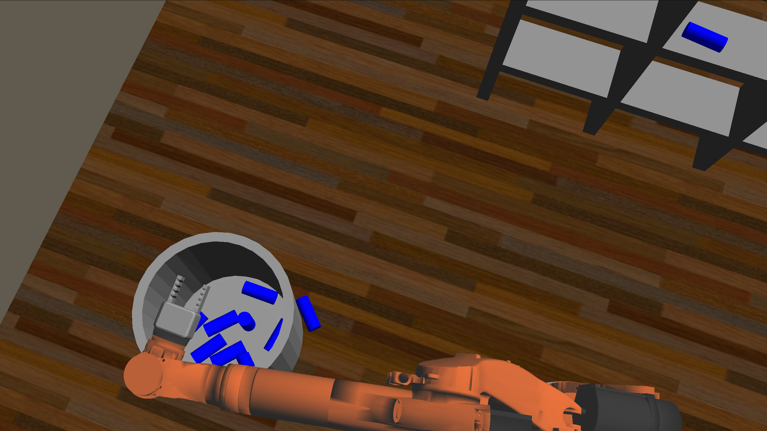
Overall, I learned a lot from this project, but the implementation is defintely not perfect. Although I managed to retrieve 8 out of 10 objects, I ran into many issues. One issue was that the arm tended to do a couple 360 degrees rotations before finally moving towards the intended target. This would somtimes result in the cylinder being knocked aside as the gripper came into position. Similarily, the robot planning tended to be ineffecient and would usually not optimize for the fastest route. Finally, sometimes the computed values for the last 3 thetas occasionally resulted in a collision with itself. It happened rarely, I saw it enough during testing that I think this is a valid concern.
Although there are still some issues with the inverse kinematics, I was able to complete the challenge of 8 out of 10 cylinders in the bucket. Therefore I would call this project a success.
 8/10 cylinders in the bucket. One was knocked over when the kuka gripper reached out and another fell when a collision occured during the path back to the bucket.