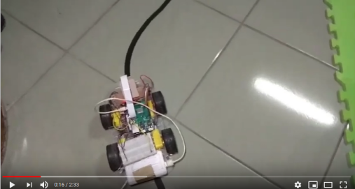
Here's description about how I build a robotic car using Raspberry PI with chassis kits and camera, also how I build / train / validate my neural network model using Tensorflow C++ API, Based on this article, I managed to get 85% accurancy when predicting images from test sets, and trained neural network model can predict centroid of lane line from the captured frames of camera (click the picture below to see the video).
- Raspberry PI 3B+
- Pi camera Rev 1.3
- car chassis kit
- L298N Dual Motor Controller
- DC motors (3-6 Volt.) x 4
- 1.2 Volt. battery x 6
- Raspbian 9 (Stretch) with GCC 6.3.0
- Build shared libraries from sources for our C++ application, this includes :
- opencv 4.0.0
- Tensorflow 1.12
- protobuf 3.6.0
please read How to build shared libraries for detail.
I decided to build my own track since I couldn't find any existing track in my hometown, it is about 6-7 meters x 4 meters, black lane line with curvatures, due to illumination changes in different time of a day and material of the floor, it could be challenging to accurately predict lane line using traditional computer vision approach.


The table below shows how I wired L298N Controller to my Raspberry PI 3B+
| L298N | RPi 3B+ |
|---|---|
| IN1 | GPIO 17 |
| IN2 | GPIO 27 |
| IN3 | GPIO 22 |
| IN4 | GPIO 23 |
| ENA | GPIO 3 |
| ENB | GPIO 4 |
I wrote a tool in Python for data collection, Here's what it does:
- recording video of my lane lines
- labeling frames from recorded videos.
- augmenting the image examples with labels.
For recording video, we mounted the camera on chassis, manually moved the car with respect to few driving situations :
- the car perfectly follows the lane line
- the car overshoot the lane line a little bit
- the car overshoot the lane line with sharp angle
To create labeled dataset, my tool extracts each frame from recorded videos to the GUI window, users can click on the frame to specify where the expected centroid of the lane line should be in each frame, then press any key on the keyboard to switch to next frame. On each key event my tool will automatically :
- resize a frame to smaller size 160 x 120
- horizontally flip the small images and the specified point in x-axis (for augmentation)
- saves the frame to image file
- normalize the point (the (x,y) in image coordinate system we just specified for the frame), the normalized (x,y) value will be in the range [-1, 1].
- append label information (normalized point & the path of the saved image) to csv file.
 |
 |
 |
 |
|---|---|---|---|
 |
 |
 |
 |
 |
 |
 |
 |
 |
 |
 |
 |
The table above shows the downsized images which will be fed into our neural network model. I ended up with 10 videos, ~15000 image examples with labels before augmentation, and ~30000 examples after augmentation.
My objective here is to build C++ based neural network application, Tensorflow C++ API seems like the easiest way to do so. A lot of similar examples on the internet descibe that you can get better training/testing result with Tensorflow python API, since many exotic / convenient operations have been implemented there (also many optimizers available), however in my case, I found that TensorFlow python API only improves 3-4% accurancy (~89%) than its C++ API (~85%, see how I define testing accurancy) with the same dataset, I couldn't get significant improvement even I applied optimizer at the python side and convolutional layer at the both side. So I still choose Tensorflow C++ API.
In the beginning I applied only 2 fully-connected to the hidden layers of the model, after some experiment I found following hyperparameters working together just fine :
- input layer size = 1800
- which means I'll crop a input RGB image from 160 x 120 to 160 x 60, then further downsize the cropped image to 40 x 15, the downsized image has 40 x 15 x 3 = 1800 features to fit into the input layer of the model.
- 1st hidden layer size = 32
- 2nd hidden layer size = 8
- output layer size = 2
- the model will output a pair of (x,y) value, which represents the normalized (x,y) number in the range [-1, 1], also means predicted centroid of lane line.
- note that I treat lane detection as a linear regression problem, NOT like logistic regression & multi-class classification, therefore the output of the model will be linear value (in the range [-1, 1]), NOT probability of different positions of centoid of the lane line.
- Tanh as activation function
- all layers, excluding the output layer, include the activation function, since we are addressing linear regression problem
- initial random value of parameter matrices, ranges from 0 to 0.0011
- learning rate = 0.00004
- lambda for regularization = 0.000001
- 2/3 of the dataset will be used for training, 1/3 of them will be for testing.
For hidden layer, I also tried few different combinations in the model :
- only 2 fully-connected layers
- 1 convolutional layer + 2 fully-connected layers
- 2 convolutional layers + 2 fully-connected layers
Due to limited resource on Raspberry PI, I cannot run that complicated neural network like YOLO or ResNet then end up eating up all of CPU/memory resource, it seems that the types of network layer we can try are limited.
The 3 options listed above provide very similar training errors, I apply the first one to my neural network model.
Before I train the model, I need to determine training / testing loss, and how do I measure accurancy. For each image example of training set, we have :
| variable name | description |
|---|---|
| x_pred | normalized value x predicted by the model |
| y_pred | normalized value y predicted by the model |
| x_true | normalized value x in the label (ground truth) |
| y_true | normalized value y in the label (ground truth) |
example_loss = sqrt( (x_pred - x_true)^2 + (y_pred - y_true)^2 );
total_loss = sum(example_loss) + lambda * sum( all_train_parameters ^ 2 );
Here is how I determine prediction accurancy, for each image example of testing set :
accurate_pred =
                 1, means the prediction is considered accurate,
                    if abs(x_pred - x_true) < 0.25  and  abs(y_pred - y_true) < 0.37
                 0, otherwise

accurancy = sum(accurate_pred) / num_of_examples_testset
I trained the model a few times on a dual-core intel i5 laptop, each time it took about 3 hrs.
In the beginning, we found the training losses can vary widely, e.g. we got previous training loss = 0.06 while current training loss = 0.120 , it turns out the reason could be skewed training set, since every time we randomly chose image examples from the entire dataset for training process, sometimes we were lucky to get a training set covering almost all kinds of lane-line conditions, while sometimes we got a training set covering only a few types of lane condition (e.g. the lanes are always in the middle in our training set).
To avoid inbalanced training/test set , we tried grouping the dataset by the similar lane-line situation, using k-mean cluster algorithm (with k = 60), then check if we need to add more images of specific types. (e.g. lack of image example with sharp left curvature ...... etc)
After this procedure the training processes works more stable, I managed to get trainning loss between 0.06 ~ 0.08, and 85% ~ 87% accurancy when predicting images from testing set using the trained neural network model
We can make use of Tensorflow C++ function tensorflow::WriteTextProto() to save the graph to protobuf-format text/binary file. To invoke this function you must prepare few arguments :
tensorflow::Envobject, created by static functiontensorflow::Env::Default()- string path to the protobuf file, it can be
std::string - get the object
tensorflow::GraphDeffromtensorflow::Scope::ToGraphDef()after you defined all the operations in the objecttensorflow::Scope
A checkpoint in tensorflow framework represents a set of trained parameters, tensorflow::WriteTextProto() will NOT save trained parameters into protobuf file, fortunately we have tensorflow::checkpoint::TensorSliceWriter instead, to do so you must do the following :
- get currently trained parameters by performing this:
Note "name_of_param_mtx1" is the string label of your parameter matrix, here in my case it's just string label of
tensorflow::Session::Run({}, {"name_of_param_mtx1", "name_of_param_mtx2",}, {}, &output_tensor)tensorflow::Variable(please see example here) , the output_tensor is a list oftensorflow::Tensorelements copying the value of trained parameter matrix. - copy raw data from each
tensorflow::Tensortotensorflow::checkpoint::TensorSliceWriter, you must prepare:- base address of the parameter raw data by calling
tensorflow::Tensor.tensor_data().data() - shape of each
tensorflow::Tensor, by callingtensorflow::Tensor::dim_size(NUM_DIMENSION). For eaxmple a 7x17 2D parameter matrix, NUM_DIMENSION can be 0 and 1, wheretensorflow::Tensor::dim_size(0)is 7 andtensorflow::Tensor::dim_size(1)is 17. - name of this checkpoint, the name must be unique from other checkpoints in one file
- create an object
tensorflow::TensorSliceby callingtensorflow::TensorSlice::ParseOrDie("-:-"), it seems that the only argument oftensorflow::TensorSlice::ParseOrDiewill be internally analyzed e.g.-:-means taking all items of a matrix. if users only want part of trained parameter matrix e.g. to only take 2nd column of all rows, then the string argument would be likely-:2, I haven't figured out such advanced uasge oftensorflow::TensorSlice::ParseOrDie.
- base address of the parameter raw data by calling
To load tensorflow graph model & corresponding trained parameters, you have tensorflow::ReadTextProto and tensorflow::checkpoint::TensorSliceReader
- the usage of
tensorflow::ReadTextProtois quite similar totensorflow::WriteTextProto(), please check out models::restore_from_file() in this repository. - To load trained parameters to the model is a little more complicated, you need to :
- before you train the model, create
tensorflow::ops::Placeholderas the entry to parameter matricestensorflow::ops::Variableinside neural network model, then define the operationtensorflow::ops::Assignwhich assigns the value fromtensorflow::ops::Placeholderto the parameter matrices intensorflow::ops::Variableof the neural network model. Your code may look like following :in the code sample above, the assigning operationtensorflow::Scope root = tensorflow::Scope::NewRootScope(); tensorflow::Output w1 = tensorflow::ops::Variable (root.WithOpName("w1"), {num_fc_inl, num_fc_l1}, tensorflow::DT_FLOAT); auto trained_w1 = tensorflow::ops::Placeholder (root.WithOpName("chkptr0_entry"), tensorflow::DataTypeToEnum<float>::v()); auto assigned_trained_w1 = tensorflow::ops::Assign (root.WithOpName("assigned_chkptr0"), w1, trained_w1);assigned_trained_w1is likew1 = trained_w1, you can consider this as another entry to initializing the parameter matrix. - when restoring the trained model, load checkpoint file by
tensorflow::checkpoint::TensorSliceReader reader ("PATH/TO/CHECKPOINT_FILE") - search for each parameter matrix by
tensorflow::checkpoint::TensorSliceReader::HasTensor()tensorflow::checkpoint::TensorSliceReader::GetTensor(CHECKPOINT_STR_LABEL, out_tensor)- and the checkpoint label: CHECKPOINT_STR_LABEL, you must give the labels you used when saving checkpoints with
tensorflow::checkpoint::TensorSliceWriter
- then you will get
tensorflow::Tensorout_tensor, which contains trained parameters, finally initialize parameters of the model with out_tensor :tensorflow::Session::Run({{LABEL_FOR_PARAM_MTX, out_tensor}}, {ASSIGN_OPS_NAME}, {}, nullptr)
- before you train the model, create
There are good online resources to learn basic concept of PID control and Pulse-Width Modulation
Once I got predicted (x,y) value from the neural network model, I applied classic Propotional-Derivative Control to converting predicted (x,y) value to duty cycle of PWM signal of the 4 DC motors.
The car speed is regulated by 2 factors :
- predicted y value
- the smaller it is (close to -1), the faster the car will move forward,
- it means the car can see the next centroid of the lane line far from its current position.
- predicted x value,
- if x is close to 0, that means the car found a relatively straight lane line, the car does not need to make a sharp turn, the duty cycle of PWM signal on both sides of DC motors will be similar.
- if x is closer to either end (1, or -1), then the steering angle will become sharper. duty cycle of PWM signal on one side will be much larger than the other side .
I found following parameters for each term of PD control (Propotional, Derivative) working together well. (following code from HERE)
    float __dt  =  1.0 * PWM_PERIOD_US * NUM_PWM_PERIODS_FOR_EACH_FRAME;
    float kp_xa =  1.0 * (90 + 5) * 0.35 ;
    float kp_xb = -1.0 * (90 + 5) * 0.35 ;
    float kd_xa =  1.0 * (90 + 5) * 280.0 ;
    float kd_xb = -1.0 * (90 + 5) * 280.0 ;
    float kp_y  =        (90 + 5) * 0.47 ;

    float error_x  =  lane_centroid_log.back().x ;
    float error_y  = (lane_centroid_log.back().y * -1.0 + 1) / 2 + 0.05;
    float error_de_dt = (error_x - pre_error_x) / __dt ;

    float p_xa = error_x * kp_xa;
    float p_xb = error_x * kp_xb;
    float d_xa = error_de_dt * kd_xa;
    float d_xb = error_de_dt * kd_xb;
    float p_y  = error_y * kp_y;

    float pid_out_a = p_xa + p_y + d_xa ;
    float pid_out_b = p_xb + p_y + d_xb ;
in the sample code above, p_xa and p_xb represent Propotional term for x ; p_y represent Propotional term for y, kp_* means parameters we tried.
My lane-line application code can be briefly seperated to 2 parts, managed by 2 different threads :
- one thread is used for always polling the camera, capturing new frame then writing into a shared
cv:Mat - the other one is for all other tasks like :
- pre-process the new captured frame
cv:Mat(resize/normalize) - feed pre-processed frame into our trained neural network model
- get predicted (x,y) pair of value from the model.
- convert the predicted (x,y) value into duty cycle of PWM signal of the 4 DC motors, using Propotional-Derivative Control.
- drive PWM signals of L298N Controller based on the duty cycle we previously got.
- pre-process the new captured frame
The 2 threads share the same frame object cv:Mat protected by mutex.
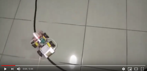
It works well as shown in following clip :
- The prediction is not 100% accurate
- I would probably try more sophisticated technique to converge training and tetsing losses, would check how optimizers are implemented in tensorflow Python API in the future.
- speed issue
- In this project I used cheap DC motors with max. working voltage 6 Volt. , and 6 NiMH batteries (1.2 Volt. for each, 7.2 Volt. in total). I would try better motors, LiPO batteries to increase voltage, and increase FPS of my PI camera to 60 or 90, if I'd like to join race competitions like Dockey Car or Formula PI...
- need more efficient way to group dataset for training / validation / test procedures
- K-mean clustering application in python takes 6 hours (k=50~60) to group entire dataset.