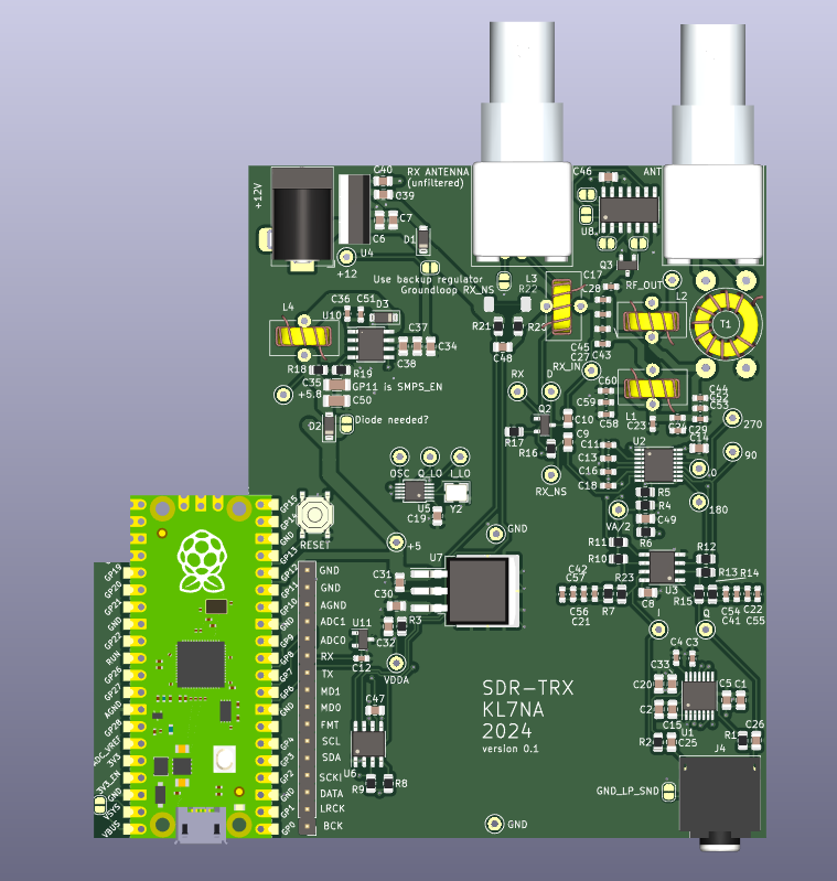
This SDR is a prototype hardware platform to assist in developing a low-cost transceiver for digital modes (FT8, JSTcall, WSPR, CW, etc) that do not require linear amplification like SSB. This is designed for amateur radio enthusiasts who view their hobby as an avenue for experimenting, who like building things, and have an interest in HF radio propagation. The idea is to use a laptop and mainstream (actively maintained) existing software as the display and for the DSP needed. The hardware described here will fill out the rest of the transceiver. The assumption is that most hams will have a PC of some kind already, and this is an easy and cheap way to get on the air using the digital modes and their PC. I am also using this as a platform to demonstrate to my students how to do an electronic design project. It is hoped a transceiver based on this prototype platform will be inexpensive enough that third-world hams or those with few funds to spend on their hobby would find it attractive. JLCPCB built five of these for me for a little over $100. This project is built using designs previously published and would not be possible without them. The next section is meant to be a short review of some of the projects I found especially useful.
- WSJT-Transceiver
- Quisk SDR Software
- WSJT-X Low S/N Digital Mode Decoding Software
- Fldigi
- DL2MAN Sandwich
- PE1NNZ uSDX
- A Comparison of Affordable Self-Assembled SDR Receivers
- QRP Labs QDX Transceiver (This transceiver is quite similar.)
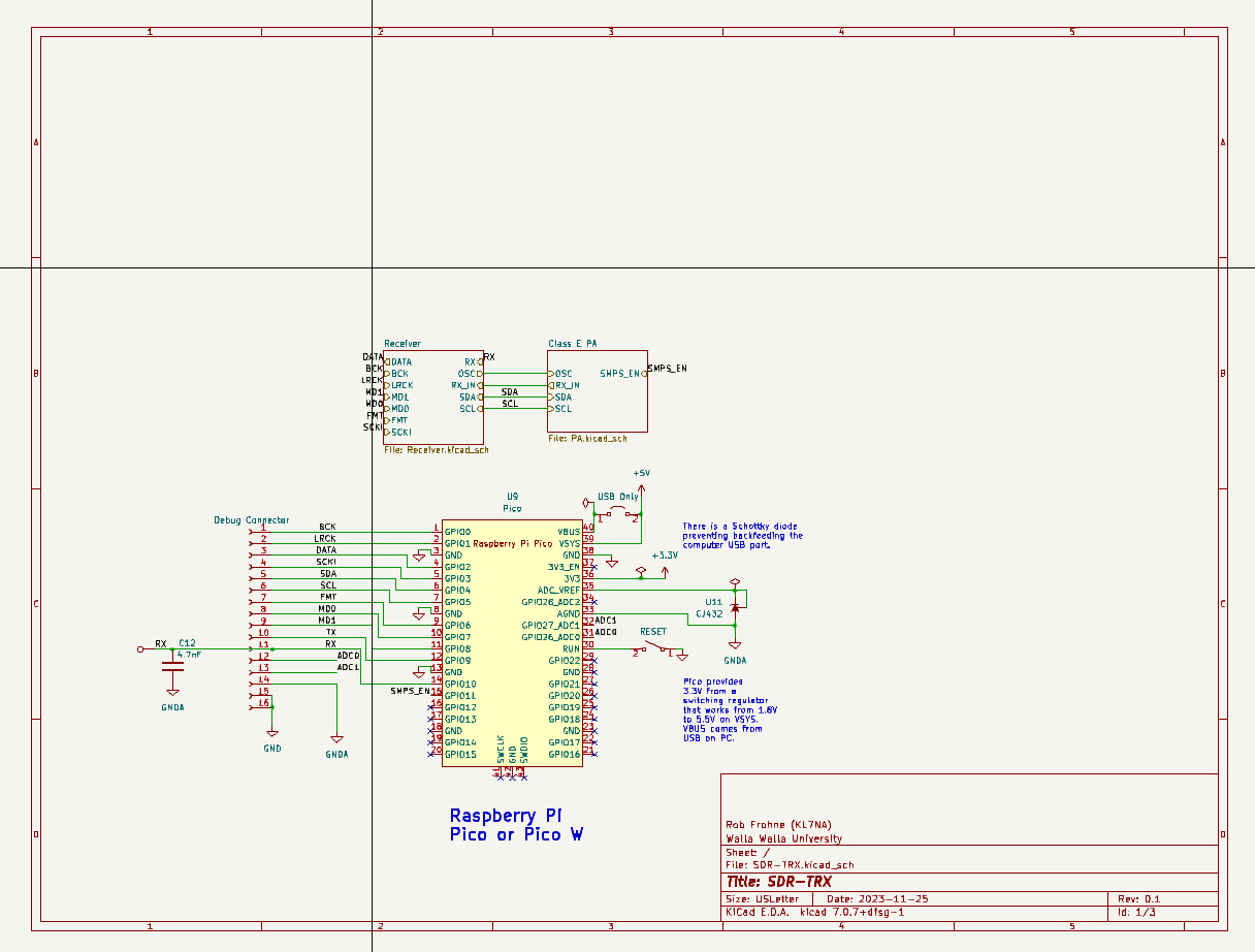
The basic block diagram showing how this SDR interfaces with a PC is shown below.
A clone of the Silicon Labs, Si5351a, the MS5351M is used as the local oscillator for the QSD down converter. The resultant audio frequency data is sent to the PC where Quisk demodulates it and sends it on to WSJT-X or Fldigi for decoding. The MS5351M's third oscillator is used to generate the digital signals on transmit. These signals are amplified by a class E circuit for the 20-meter band. Throughout the unit, there are features that provide stepping stones toward the final goal. For example, an output is provided to allow the sound data to be sent to the PC where a sound card on the PC converts the sound signal to digital samples. A Raspberry Pi Pico or Pico W is used on the SDR to control the MS5351M local oscillator and exciter, sample the receiver audio data using a PCM1808 ADC, and send the sampled data to the PC for processing. It also receives transmit data from the PC to allow transmission of the digital signals desired.
The Kicad project SDR-TRX contains the hardware documentation, including the schematic diagram and the printed circuit board. The software is still in development.
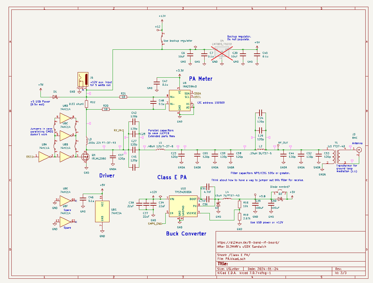
The MS5351M, a Si5351a clone, generates a digitally transmitted signal (and the harmonics you expect) on its third output. It is used to drive a set of CMOS inverters that in turn drive a MOSFET class E amplifier for 20 meters.
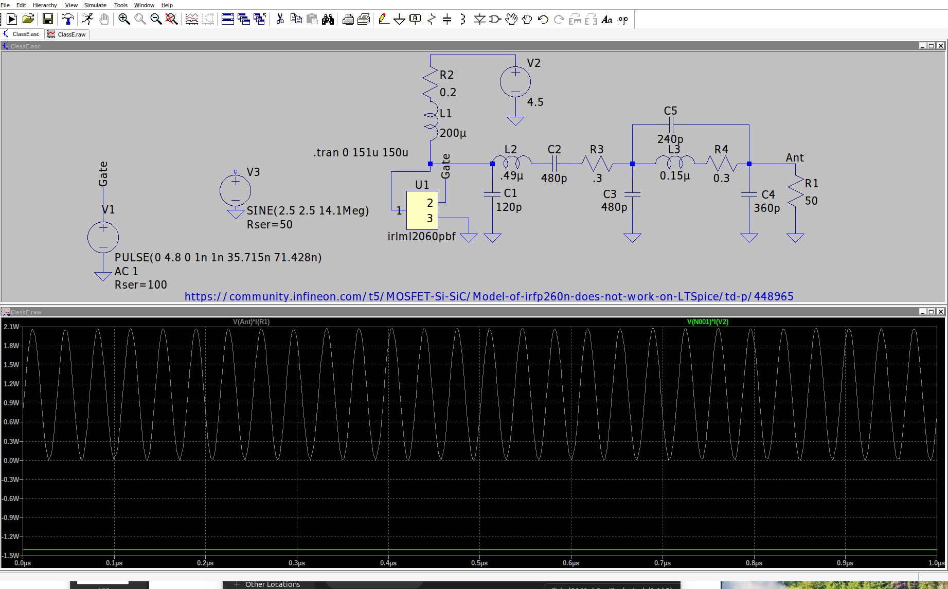
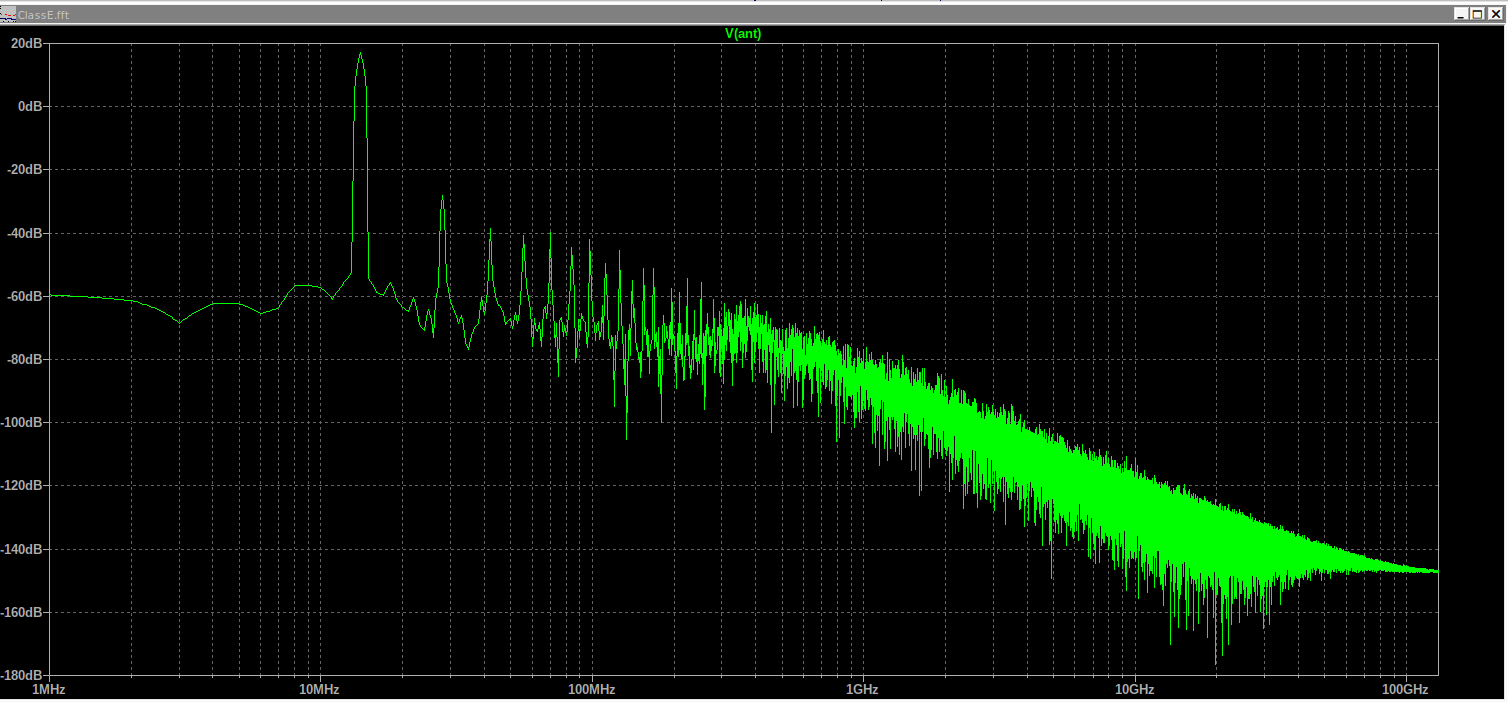
The design started with the DL2MAN sandwich Class E amplifier for 20 meters. LTspice was employed to try and minimize the number of values of Extended Parts capacitors needed from JLCPCB while still maintaining a decent efficiency, power output, and harmonic attenuation. The value of the capacitor that seemed to be best was a 120 pF 100V 1% COG multilayer monolithic capacitor. We paralleled a bunch to make the amplifier we ended up with. It was chosen first for harmonic suppression, second for power output, and lastly for efficiency, with the constraint of using only one value of capacitor. The simulation has about 50 dB of harmonic attenuation, about a watt of output, and an efficiency of 75%. See the simulation below which is called Class E.asc in the Simulation folder.
This simulation shows the efficiency and output power.
This is the FFT of the antenna voltage.
There is an I2C voltage and current monitor, the INA219A, that should allow measuring the DC power used by the class E amplifier so LTspice simulations can be verified for accuracy easily.
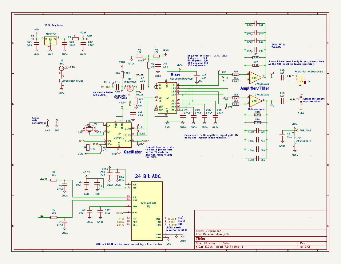
The receiver used was the QSD Tayloe-type design using both inverting and inverting inputs. The inverting input has a lower input impedance and so is more of a current amplifier. The non-inverting amplifier has a high input impedance, and so acts as a voltage amplifier. The low-frequency gain of the inverting amplifier is
The MS5351M generates in-phase and quadrature signals for the SN74CBT3253 four-to-one analog switch mixer.
The sampling capacitors provide a low pass filter for the signal, and the cutoff frequency is
There are two antenna inputs (BNC connectors), one on a transmit/receive switch that uses the Class E filter to try and filter the received signal, and another one that bypasses the filter that can be used when we want to listen to more than just 20 meters. It can also suffice to do real-world testing to see which is preferable.
An LDO linear regulator powered by the USB 5 volts or the external 12-volt power supply provides a 4.5 volt low noise power for the analog parts in the receiver. When the 12-volt input is used the USB power supply is disconnected by some Schottky diodes and two possible regulators drop the voltage to about 5.8 volts to run the rest of the radio except the class E PA stage. These are selected by an I/O line from the processor or by not populating the undesired supply. The two options are an SMPS buck regulator or a 7805 linear regulator that is not as efficient but should not produce switching noise. We will experiment to see which we like and choose that one.
There are several ground loop suppression strategies available. The filtered antenna uses a transformer. In other places, a jumper is provided to allow a single ground connection through the power supply.
The control of the SDR comes from the operator via the PC interface software (Quisk, for example), which sends the data to the SDR via USB UART or via WIFI. The MCU that we chose is the Raspberry Pi Pico or Pico W if WIFI is desired. It controls the MS5351M programmable oscillator using I2C and uses the INA219 to measure the current and voltage of the power amplifier. It also reads the ADC via I2S and transfers that data to the PC where Quisk or a similar program demodulates it. For the Pico, we are using C++ and the Earl E. Philhower, Arduido-Pico development library. The easiest way to get started is to use the Arduino IDE, but VScode with Github Copilot there are a lot more features. You have to read how to make the Arduino-Pico code work with VScode. The software needs a lot more attention, but that is the point of a software-defined radio.
The PCB has test points and uses components I found still available on JLCPCB. That accounts for why a mix or 0603 and 0805 components, and why there are a lot of 120pF and 4.7nF caps in parallel.
The cutout is for the WIFI antenna if a Pico W is used.

