Term1-Project4: Advanced lane lines detection
- Compute the camera calibration matrix and distortion co-efficients give a set of chessboard images
- Apply a distortion correction to raw images
- Use color transforms, gradients,etc to create a thresholded binary images
- Apply a perspective transfor to rectify binary image
- Detect lane pixels and fit to find the lane boundary
- Determine the curvature of the lane and vehicel position wieth rescpect to center.
- Warp the detected lane boundaries back onto the original images
- Output visual display of the lane boundaries and numerical estimation of the lane curvature and vehicle position.
Rubric Points
Here I will consider the rubric points individually and describe how I addressed each point in my implementation.
1. Provide a Writeup / README that includes all the rubric points and how you addressed each one. You can submit your writeup as markdown or pdf. Here is a template writeup for this project you can use as a guide and a starting point.
You're reading it!
1. Briefly state how you computed the camera matrix and distortion coefficients. Provide an example of a distortion corrected calibration image.
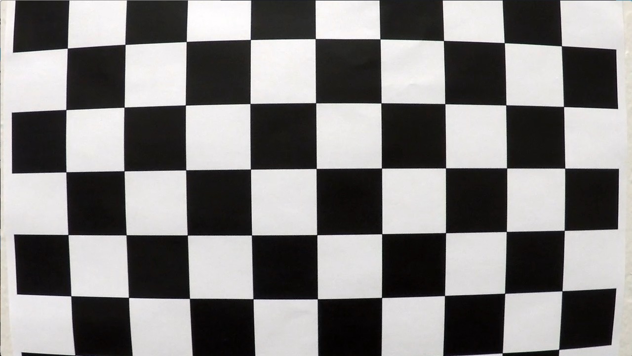
The calibrate_camera() method implemented in the second cell of the python notebook performs the camera calibration. It uses the OpenCV methods findChessboardCorners() and calibrateCamera() to find the clibration matrix and distortion coefficients. The findChessboardCorners() method takes in a distorted and grayed checkerboard image along with number of internal corners and returns image points. This is done for all the image in the set of checkerboard images and these image points along with their corresponding object points are provided to calibrateCamera() method which returns the calibration matrix and distortion coefficients.
The undistort() warapper method takes in an image along with the calibration matrix and distortion coefficients and returns a rectified image using the OpenCV's undistort() method.
A sample distorted calibration checkboard image and its distortion corrected image is as shown below
| Distored image | Rectified image |
|---|---|
 |
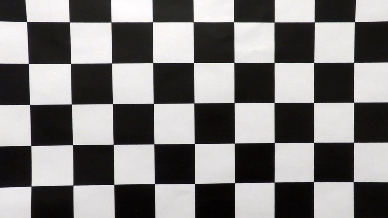 |
The python notebook shows these corrections for all the checkboard images used.
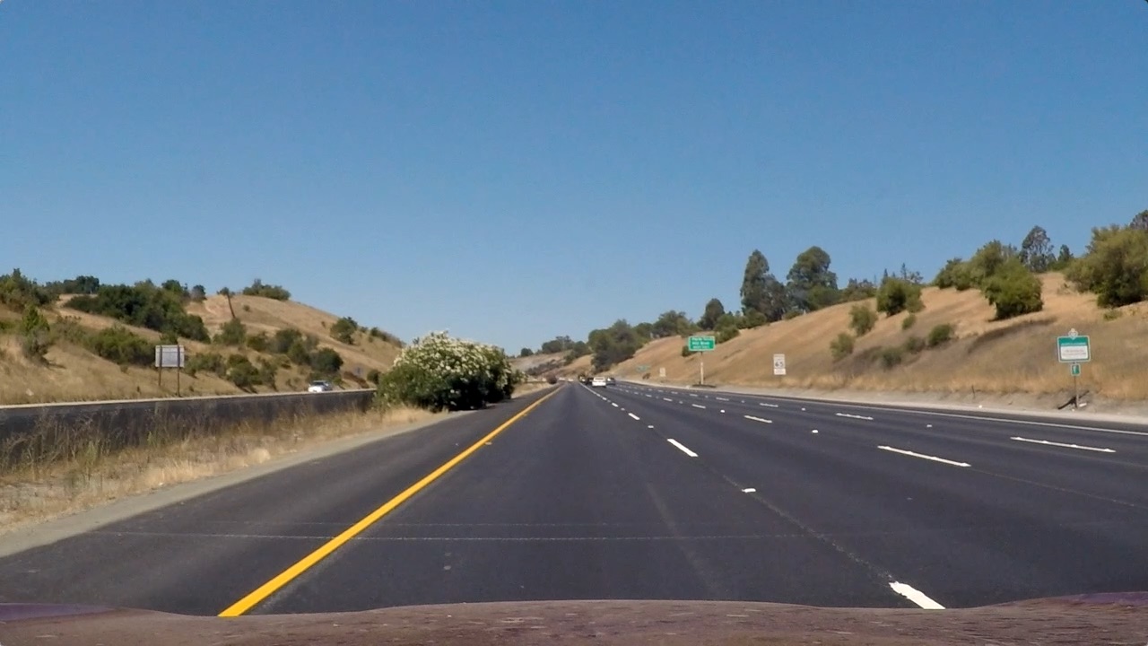
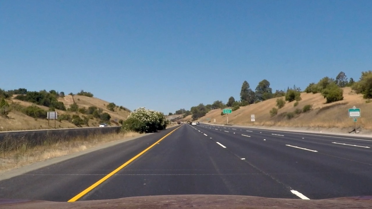
The same camera that we calibrated above is used for capturing the images from the car. Therefore, use the undistort() method with calibration matrix and distrotion coefficients to rectify all the images from the video. The sample demo of a image from the project video and its rectified image is as shown below
| Original image | Rectified image |
|---|---|
 |
 |
2. Describe how (and identify where in your code) you used color transforms, gradients or other methods to create a thresholded binary image. Provide an example of a binary image result.
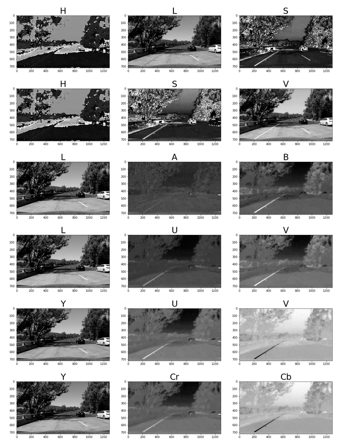
The below image shows a sample of all the color spaces that were explored to be considered for combining with sobel gradients.
clearly, the 'S' & 'B' channels from HLS & LAB color spaces accordingly stood out for the combination of white & yellow lane lines. These channels were thresholded to account for different lighting conditions as shown below.
To these thresholded s+b channels, I then applied sobel gradients to identify the lines. The result of multiple combinations of sobel gradients being applied to the s+b channel images is as shown beow.
The combination of sobel mag & dir seemed to produce the best results and were hence considered to be used for the processing pipeline.
The python notebook cells 5,6,8 shows these filtering applied to different test images.
3. Describe how (and identify where in your code) you performed a perspective transform and provide an example of a transformed image.
The unwarp() method implemented in cell 7 in the python notebook perform the perspective transform. It takes in a image to be transformed along with source & destination points and returns a perspective transformed image. Internally, it uses the OpenCV methods 'getPerspective()' and 'warpPerspective()'.
The following source & destination co-ordinates were applied to all the images.
| source | destination |
|---|---|
| (550,464) | (450,0) |
| (750,464) | (w-450,0) |
| (250,682) | (450, h) |
| (1110, 682) | (w-450,h) |
Below is the sample of an unwarped image.
The method pipeline() in the python notebook implements all the above mentioned steps to create a processing pipeline for the images.
4. Describe how (and identify where in your code) you identified lane-line pixels and fit their positions with a polynomial?
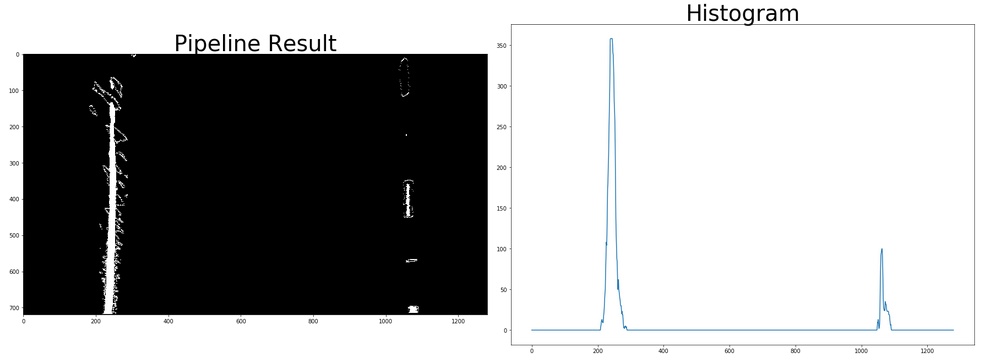
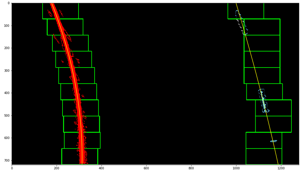
The methods named 'sliding_window_polyfit()' and 'polyfit_using_prev_fit()' implemented in the python notebook performs the lane pixels detection and fitting a polynomial curve to them. The process is based on using the histogram of the perspective transformed binary image from the pipeline to identify the bottom most X postions of the left & right lanes. Then, the image is split into 10 equivalent windows and for each window, the lane pixels are identifed centered on the midpoint of the pixels from the window below. This follows the lane from the bottom to the top of the image. For the pixels identified by this process, the numpy method 'polyfit()' is used to fit a second order polynomial to represent the lane curve.
The image below show the histogram from one of the sample test frames.
The below image shows a sample of the result from the sliding window polyfit method.
The polyfit_using_prev_fit() performs the same task as sliding_window_polyfit(), but only searches for lane pixels within a certain range of the fit from the previous frame.
5. Describe how (and identify where in your code) you calculated the radius of curvature of the lane and the position of the vehicle with respect to center.
The method 'calc_curvature_radius_and_center_distance()' performs the calculation of the radius curvature and distance from the lane center as per the methods based on this website.
curve_radius = ((1 + (2*fit[0]*y_0*y_meters_per_pixel + fit[1])**2)**1.5) / np.absolute(2*fit[0])
In this example, fit[0] is the first coefficient (the y-squared coefficient) of the second order polynomial fit, and fit[1] is the second (y) coefficient. y_0 is the y position within the image upon which the curvature calculation is based (the bottom-most y - the position of the car in the image - was chosen). y_meters_per_pixel is the factor used for converting from pixels to meters. This conversion was also used to generate a new fit with coefficients in terms of meters.
The position of the vehicle with respect to the center of the lane is calculated with the following lines of code:
lane_center_position = (r_fit_x_int + l_fit_x_int) /2
center_dist = (car_position - lane_center_position) * x_meters_per_pix
r_fit_x_int and l_fit_x_int are the x-intercepts of the right and left fits, respectively. This requires evaluating the fit at the maximum y value (719, in this case - the bottom of the image) because the minimum y value is actually at the top (otherwise, the constant coefficient of each fit would have sufficed). The car position is the difference between these intercept points and the image midpoint (assuming that the camera is mounted at the center of the vehicle).
6. Provide an example image of your result plotted back down onto the road such that the lane area is identified clearly.
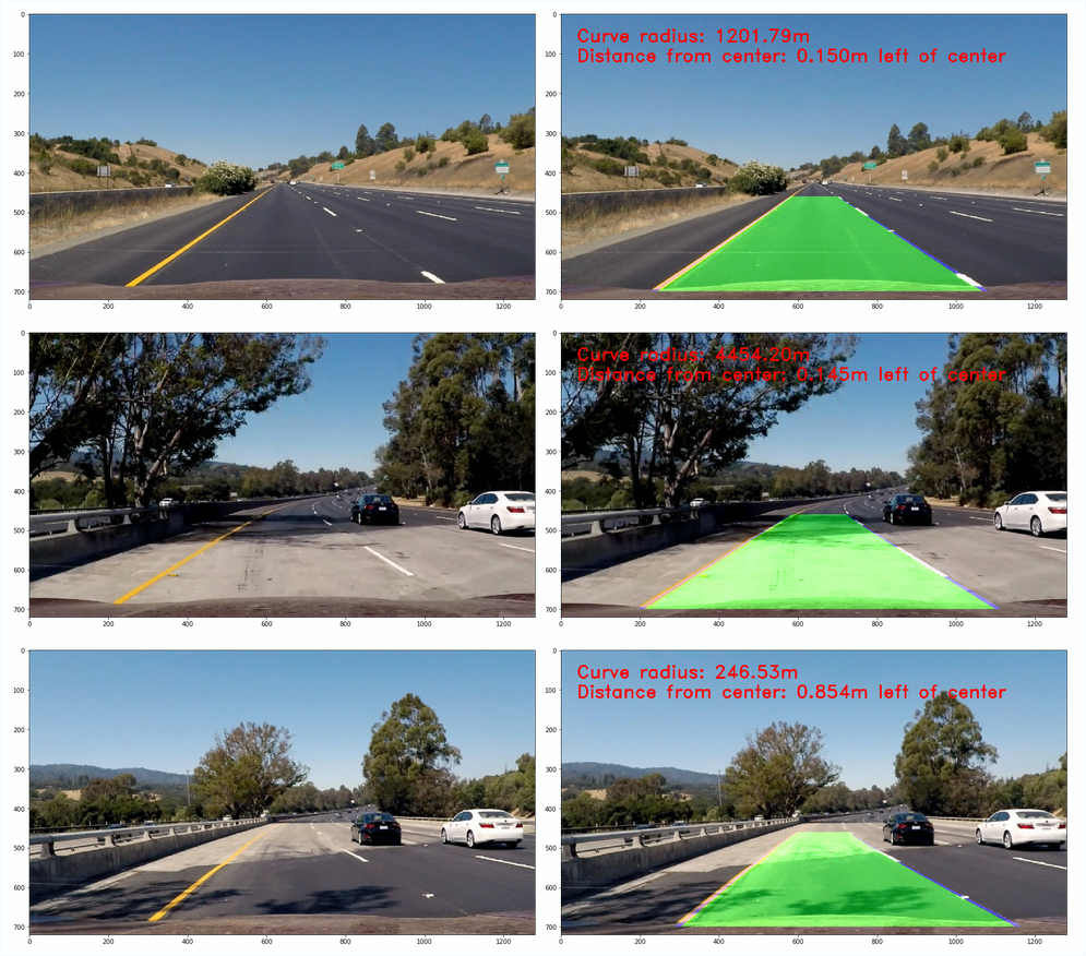
The methods draw_lane() and show_curve_data() draws the identifed lanes and the calculated curvature metrics on the original image. The lane is a polygon generated from the left & right fits, warped back onto the perspective of the original image using the inverse perspective matrix obtained from the unwarp() method.
Here is the sample of the result.
1. Provide a link to your final video output. Your pipeline should perform reasonably well on the entire project video (wobbly lines are ok but no catastrophic failures that would cause the car to drive off the road!).
Here's a link to my video result (project_video_ouput.mp4)
1. Briefly discuss any problems / issues you faced in your implementation of this project. Where will your pipeline likely fail? What could you do to make it more robust?
The different lighting condition and the combination of the road & lane colors presented the major problem. Although the S & B channels does a good job of isolating and filtering the lane lines, their effective results are based on having no obstruction on the road and the road having a similar surface through out. For example, in the challend video, the car's lan contains different shades of road which also show up as edges. Another scenario is when a bright/white car is moving is the adjacent lanes and is brighter than the lane colors. In such scenarios, the filtereing based on the color channels completely breaks down and I haven't yet found a better alternative.
Apart from this, I also faced difficulties & error while unwarping a section which had a vehicle/shadow in the region of interest. the inclusion of such vechicle/shadows also result in linear vertical lines and when these are found close of the lane lines, they cause ambiguity, especially in cases when lane colors are dull compared to these objects. I tried several values for thresholding, but none seemed to have good effect in such scenarios. When I tried the pipeline on road condition in India, the pipeline failed completely since the lane markes vary in size, colors and continuity.
The pipeline implemented here seems trivial and I hope to return to this problem and evaluate the current state-of-art on lane keeping/tracking.
- The readme file had wrongly linked the undistorted image link to the distorted image. This was corrected.
- src & dest poitns for the region of interest was changed based on the reviewer's suggestion. Along with corresponding modifications, this drastically improved the perforamce.
- The detected lane fit is now drawn on the undistorted image instead of the original distorted image.(I had previously misunderstood the rubric's requirement of 'original image' as the original distorted image from camera)
- In the result video, the lanes are drawn on the undistroted image
