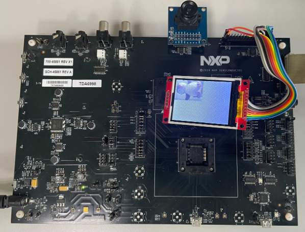
This application note describes how to use the FlexIO to emulate the parallel camera interface to receive real-time image data from a camera device based on i.MX RT1010.
Due to the limited RAM buffer size, the frame size is configured to QQVGA (160*120).
Please refer to AN12686 for complete instructions on how to use this software.
FlexIO is highly configurable. It allows you to implement a variety of functions, including:
- Emulation of serial communication interfaces, such as UART, SPI, I2C, I2S, and so on.
- Emulation of parallel communication interfaces, such as the camera interface, Motorola 68K bus, Intel 8080 bus, and so on.
- Generation of PWM waveforms.
- Implementation of logic functions.
- Implementation of state-machine functions.
This demo is built based on NXP MCUXpresso SDK. And this repository contains all required source files.
- MCUXpresso SDK: 2.5.0
- IAR Embedded Workbench for ARM: 9.30.1
- EVBMIMXRT1010 Rev A board
- OV7670 camera module
- ILI9341 LCD module
- Personal Computer
- J-Link Debugger
- Micro USB cable
-
Prepare the EVBMIMXRT1010 board:
- short R45 pin2 & pin3;
- short R46 pin2 & pin3;
- short R47 pin2 & pin3;
- short R51 pin2 & pin3;
- short R52 pin2 & pin3;
- short R56 pin2 & pin3;
- short R70 pin2 & pin3;
- short J33 pin3 & pin4, pin5 & pin6, pin7 & pin8 with jumpers;
- short J34 pin4 & pin5, pin7 & pin8, pin10 & pin11, pin13 & pin14, pin16 & pin17 with jumpers;
- short J35 pin1 & pin2, pin4 & pin5, pin7 & pin8, pin10 & pin11, pin13 & pin14, pin16 & pin17 with jumpers;
-
Connect the OV7670 camera module with J45 of EVBMIMXRT1010.
-
Connect the ILI9341 LCD module with J46 pins of EVBMIMXRT1010 by using wires.
EVBMIMXRT1010 ILI9341 LCD module BOOT_3V3 - J46-30 VCC - PIN1 GND - J46-29 GND - PIN2 SPI_CS_Touch - J46-23 CS - PIN3 GPIOMUX_IO7 - J46-1 RESET - PIN4 GPIOMUX_IO8 - J46-2 DC/RS - PIN5 SPI_SDO - J46-26 SDI/MOSI - PIN6 SPI_SCK - J46-24 SCK - PIN7 GPIO2_IO13 - J46-28 LED - PIN8 SPI_SDI - J46-25 SDO/MISO - PIN9 -
Connect J-Link debugger with J36 or J37 of EVBMIMXRT1010.
-
Build a configuration and download the program to the target board.
When the demo runs successfully, the camera frames are shown in the LCD panel.
If you have questions, please create a ticket in NXP Community.
Questions regarding the content/correctness of this example can be entered as Issues within this GitHub repository.
Warning: For more general technical questions regarding NXP Microcontrollers and the difference in expected funcionality, enter your questions on the NXP Community Forum
| Version | Description / Update | Date |
|---|---|---|
| 1.0 | Initial release on Application Code Hub | August 10th 2023 |


