AN13509 briefly describes the principle of drawing using GPU and MIPI DSI, and measures the power consumption and frame rate of drawing and pushing screens under different conditions.
Please refer to AN13509 for complete introduction on how to use this software. https://www.nxp.com.cn/docs/en/application-note/AN13509.pdf.
i.MXRT595 is a dual-core microcontroller combined a graphics engine and a streamlined Cadence® Tensilica® Fusion F1 DSP core with Arm® Cortex®- M33 core. It offers an embedded solution for smart watch or other display device due to the role of GPU.
Power consumption and frame rate are the considerations for performance evaluation during pushing screen. These two points are affected by many factors, such as the number and location of frame buffer and complexity of graphics. This document illustrates graphics drawing methods and performance comparisons under different conditions.

This document briefly describes the principle of drawing using GPU and MIPI DSI, and measures the power consumption and frame rate of drawing and pushing screens under different conditions.
The software for this Application Note is delivered in raw source files and MCUXpresso projects. Software version:
- SDK: v2.9.2
- IDE: MCUXpresso IDE v11.4.0
- Micro USB cable
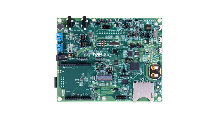
- EVK-MIMXRT595 SCH-45800 REV D1 board( https://www.nxp.com/design/development-boards/i-mx-evaluation-and-development-boards/i-mx-rt595-evaluation-kit:MIMXRT595-EVK )
- Personal Computer
- G1120B0MIPI smart MIPI panel( https://www.nxp.com/design/development-boards/i-mx-evaluation-and-development-boards/1-2-wearable-display-g1120b0mipi:G1120B0MIPI )

- Connect MIPI panel to J44.
- Connect a USB cable between the host PC and the OpenSDA USB port(J40) on the target board.
- Open a serial terminal with the following settings:
- 115200 baud rate
- 8 data bits
- No parity
- One stop bit
- No flow control
- Download the program to the target board.
- Either press the reset button on your board or launch the debugger in your IDE to begin running the demo.
There are two kinds of graphics to display. One is a tiger and the other is a clock. We can set different images, different frame buffer numbers, and different frame buffer locations to observe the power consumption in this scenario.
For power observation points, the 4.3 section in AN13509 gives the detailed description,please refer to it.
Bekow are the simple graphics and complex graphics examples.


For the frame rate and power consumption result in the different scenario, please refer to AN13509.
Questions regarding the content/correctness of this example can be entered as Issues within this GitHub repository.
Warning: For more general technical questions regarding NXP Microcontrollers and the difference in expected funcionality, enter your questions on the NXP Community Forum
| Version | Description / Update | Date |
|---|---|---|
| 1.0 | Initial release on Application Code HUb | June 13th 2023 |