On-device trainable anomaly detection based on the MCX platform. Train the SVM model on-device with normal accelerometer data and inference SVM model on-device too.
Because data patterns are often very different or vary among the device life cycle.
During the whole life cycle of a device, learning may need to be done multiple times.
The GUI is implemented by LVGL.


- Download SDK_2_14_0_FRDM-MCXN947
- Download and install MCUXpresso IDE V11.9.0 or later.
- 3.5" Low Cost NXP LCD (Default) or Mikroe TFT PROTO 5" Capacitive
- FRDM-MCXN947(SCH-90818_REV B) board
- IMU(Inertial Measurement Unit) Sensor: MPU6050 module or FXLS8974 ACCEL-4-CLICK
- FAN
- Type-C USB cable
- Connect board with LCD

Or Mikroe TFT PROTO 5" Capacitive

- Stick the IMU(6050) Sensor on the FAN like:

or IMU(FXLS8974)

- Connect IMU with FRDM-MCXN947 board, connection is shown in the table:

- Connect LCD Panel with J8 FRDM-MCXN947 board.
- The whole system is shown as:
IMU(MPU6050)

or IMU(FXLS8974)

Connect the debug port on board with the laptop.

Import the project into MCUXpresso IDE, click 'Import project from Application Code Hub', search 'on-device training fan anomaly on mcxn947' example, and clone to the local workspace.

If use Mikroe TFT PROTO 5" Capacitive, set 'LCD_SSD1963=1' in PreProcessor in project setting.
Build the project, after compilation is complete, use the GUI Flash Tool (2 in the following figure) to write the program to the board.

In VS code, select the 'MCUXpresso For VScode' plugin, and click 'Application Code Hub' in the QUICKSTART PANEL. search 'on-device training fan anomaly on mcxn947' example, clone to local workspace.
After a while, the project is shown in the 'Projects'.

If use Mikroe TFT PROTO 5" Capacitive, set 'LCD_SSD1963=1' in PreProcessor in project setting.
Build the project, after compile complete flash the board.

Reset board, the main windows showing as:

Set the fan in the normal state, click the 'Train' button, and enter the training window.

Click the start button to start training. Notice that don't move or touch the fun during the training.
After training is complete, click return back to the main window. The window shows the normal status, Green LED at the top is on.

Flip the Fan over, then the data of IMU is changed, and then the normal status is detected. The red LED at the top is on.

- Cover the fan then anomaly state is detected.

- Retrain the model, after training complete state is normal.

- Remove the cover, then the anomaly state is detected.

For more details about the demo, please refer to the video.
(image/how_to_run.mp4).
The 'Param' setting in training windows.
The Gam is “Gamma (γ)”, Nu is “Nu (ν)”, they are two parameters to tune the trade-off between sensitivity and tolerance of the trained model.
For most demo settings, the default values (Gam:0050, Nu:0.1) often lead to a reasonable tradeoff between sensitivity and tolerance.
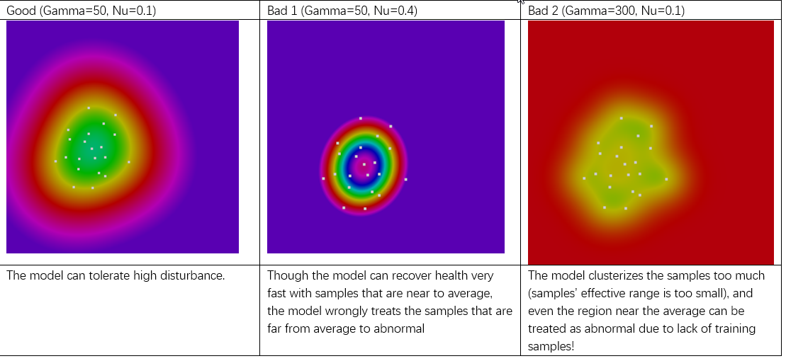
- With larger Nu, the model is more sensitive to data change, but very large Nu (such as >=0.4) can make the model treating some training samples that are far from average as abnormal! So if you want a high sensitivity and quick-response demo, you should use larger Nu (such as 0.1 to 0.4); but if you want the demo more tolerant to random or accidental disturb, you should use smaller Nu (such as 0.03 to 0.1)
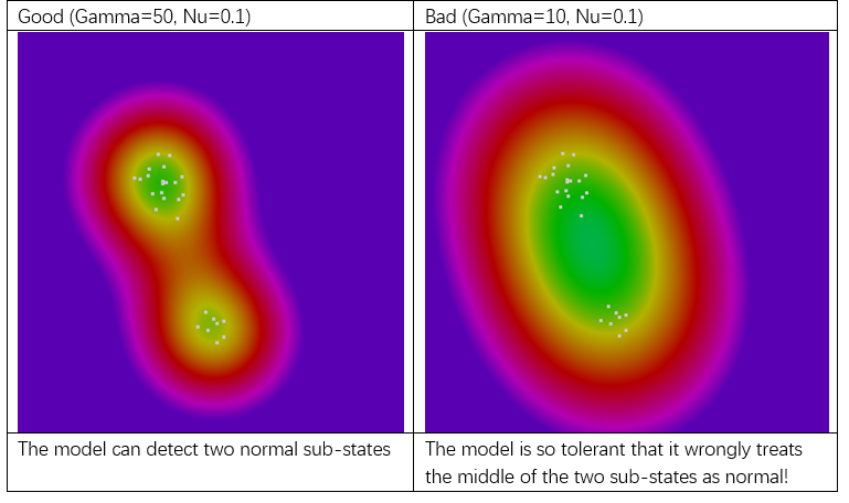
- With larger Gamma, the model tends to treat the training data to multiple clusters (each training sample’s effective range gets smaller), So if your normal state contains multiple sub-states (such as both fan-off and fan-on are normal), then you should use larger Gamma (such as 20 to 200); but larger Gamma also makes the model less robust to the randomness in training data, so if your demo environment is heavily disturbed (such as by the vibration of a working computer, the air vibration by nearby fans, walking persons nearby), you should use smaller gamma (such as 5 to 20).
2D color contour visualization of the model’s decision boundary on the LCD, the color in green to blue are normal region, while the color in yellow-red-purple are abnormal regions. Default setting such as

-
Example 1: Two normal sub-states that are significantly different
-
Example 2: One normal sub-state, but data variance is large (due to disturbances)


Note: The model is the “one-class Support Vector Machine”, below are some more technical-oriented explanation of Gamma and Nu: Gamma (γ): Gamma is a parameter of the kernel function that determines the distribution of data after it is mapped to a higher-dimensional space. In the Radial Basis Function (RBF), a larger gamma value implies a smaller decision boundary, making the model more focused on the local characteristics of the training data; whereas a smaller gamma value suggests a larger decision boundary, resulting in a smoother model that is less sensitive to local fluctuations in the training data. Nu (ν): Nu is a user-defined parameter that represents the upper limit of the proportion of error data points and the lower limit of the margin. This parameter helps control the ratio of support vectors as well as the looseness of the decision boundary. Simply put, a smaller nu value makes the model more inclined to ignore more outliers, leading to a wider decision boundary; conversely, a larger nu value makes the model more inclined to include more data points, resulting in a narrower decision boundary.
Please contact NXP for additional support.
Questions regarding the content/correctness of this example can be entered as Issues within this GitHub repository.
Warning: For more general technical questions regarding NXP Microcontrollers and the difference in expected funcionality, enter your questions on the NXP Community Forum
| Version | Description / Update | Date |
|---|---|---|
| 1.0 | Initial release on Application Code Hub | January 30 th 2024 |