This is the final project of EECS 461 in University of Michigan. The goal of the project is to simulate Auto steering and Adaptive Cruise Control.
ACC and self-steering are more and more used in automotive industry. Like recently, Honda implements Honda Sensing in 2016 in its new civic and accord. In this project, we use embedded system to achieve the same functions for a virtual vehicle. We use Simulink to establish vehicle models, and generating C code for the embedded system. The car can be driven by human, or work in ACC mode to keep a speed or distance from the vehicle ahead. Also, the car can be self-steering to keep in the middle of the road.
There are six file you would have in this project
- DrivingSimVR: Folder that contains the Windows graphics program
- parameters.m: MATLAB script to set model parameters
- Final project TEMPLATE.slx: Template Simulink model for the Project
- controllers.slx: Contains a position and a speed controller
- rappid_564xl_user_copy_required_files.m: place in the same folder as the main project Simulink file.
- Demo.mp4: show the result of ACC and auto-steering
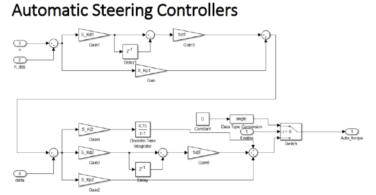
Automatic Steering Controllers
Inputs of automatic steering controller are enable command, desired lateral displacement (a constant value, n_des), actual lateral displacement (n), steering angle (delta). The output of this block is auto steering torque. A discrete time PD controller is implemented to get a reference angle. Then the error between this reference angle and delta would go through a discrete time PID controller which yields an output value of the auto torque. When tuning the value of controllers, we followed the method that if the car make multiple attempts to make a turn, the result is underdamped, the value of Kp should be increased; if the oscillation is unstable, the value of Kp should be decreased. If there is a big oscillation and it takes a long time to get the car stable, the value of Kd should be increased to make the oscillation small. The value of Ki was very small.
In the end, we got the values of the gains as follows: S_Kd1=0.045; S_Kp1=0.45; S_Kp2=600; S_Ki2=0.0001; S_Kd2=80.
Adaptive Cruise Control
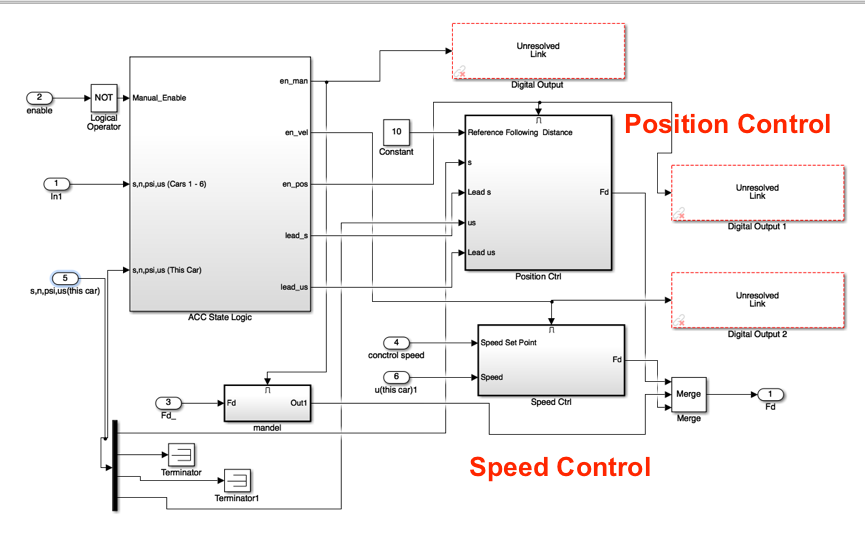
There are three modes of operation for the ACC system. If the system is deactivated, then the vehicle is under manual control, with the potentiometer functioning as a \gas" pedal. When ACC is turned on, there are two modes of operation: there is a \speed control" mode that maintains the vehicle at the desired velocity unless another vehicle is too close, in which case a \position control" mode is implemented that keeps the vehicle aixed distance from the car immediately in front. The ACC system is actually two controllers with some logic that selects one of the two controllers or selects manual control if the system is deactivated. The switching logic needs to know the s coordinate of the lead vehicle, so you must create a subsystem that takes the s coordinates from all the other vehicles, compares them against your own s-coordinate, and selects the lead vehicle if one exists. If there is no lead vehicle, then the switching logic activates the speed control block. Let subscript i denote the lead vehicle. Then given a lead vehicle s-coordinate si and your own s-coordinate s and the speeds usi and us, a simple switching logic can be defined by
where H is the safe gap distance. This switching logic may tend to introduce oscillations between modes, so it may be useful to use additional logic to prevent switching out of position control mode until the value of (usi - us) exceeds a small positive amount
The ACC enables either position or speed control if activated, or manual control otherwise. In Simulink this is accomplished by using either a State ow diagram or an \enabled subsystem," which only runs if the enable signal is 1. The three possible subsystems all produce a force Fd to drive the vehicle's front wheel. Use a Simulink \merge" block to select the output of the one enabled subsystem.
CAN Communication
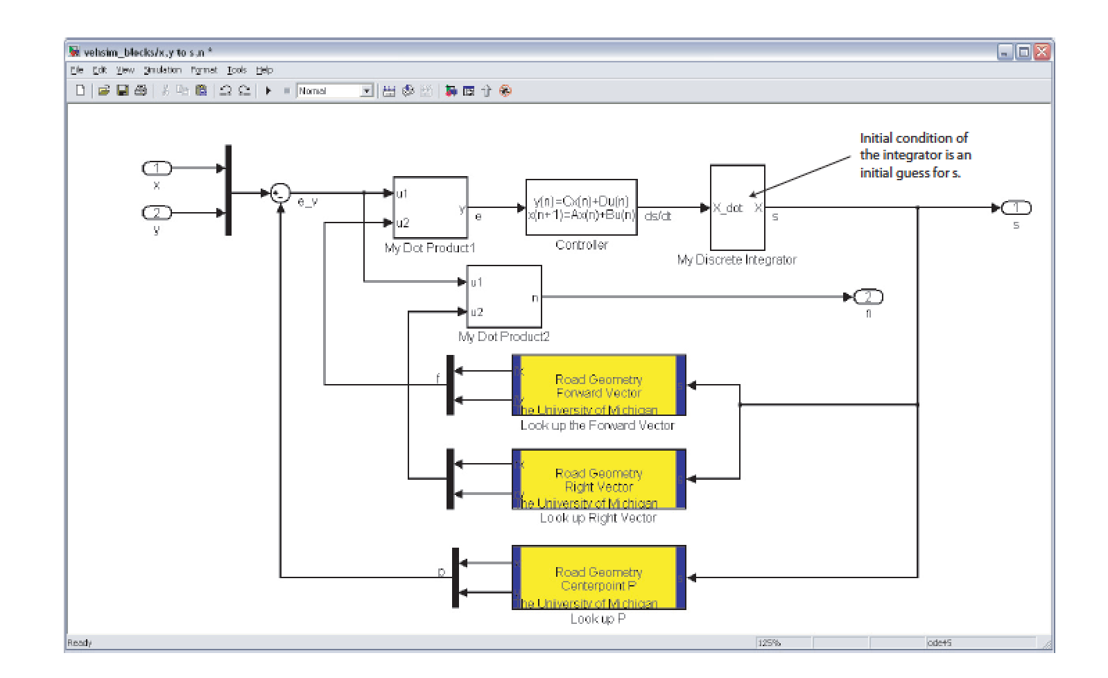
In an actual ACC system, radar would be used to measure relative location and velocity of traffic in front of the vehicle. In this lab, we will replace radar information with communication between vehicle models by using the CAN network. Each computer on the CAN network will periodically transmit 4 values (32-bits each) onto the network. The ACC systems need the speed along the centerline us (see Section 4) and the s-coordinate of all the other vehicles. The graphics software needs x, y and delta for each vehicle, where x and y can be found from s and n. To provide these values s, n, us, and delta , each lab station must transmit 2 64-bit Messages (with two 32-bit values per message). Also, the format of these messages must be standard so that everyone can understand each others messages, so the following format must be used.
- Message 1, Bytes 1-4: s as a float
- Message 1, Bytes 5-8: n as a float
- Message 2, Bytes 1-4: us as a float
- Message 2, Bytes 5-8: delta as a float in radians
To form the CAN messages, use the \Single-to-Bytes" block to create two 4-byte arrays and then mux them into the port data of the CAN transmit block. When receiving CAN messages, they can be unpacked by an inverse operation. The data can be demuxed into an array of 8-bytes and then the upper and lower bytes are muxed into 4-byte arrays and passed to the \Bytes-to-Single" block to reconstruct the oating-point value.


