Copyright (c) 2019 ETH Zurich, Georg Rutishauser, Lukas Cavigelli, Luca Benini
This repository contains the open-source release of the hardware implementation of the Extended Bit-Plane Compression scheme described in the paper "EBPC: Extended Bit-Plane Compression for Deep Neural Network Inference and Training Accelerators". Two top-level modules are provided: An encoder and a decoder. The implementation language is SystemVerilog.
If you find this work useful in your research, please cite
@article{epbc2019,
  title={{EBPC}: {E}xtended {B}it-{P}lane {C}ompression for {D}eep {N}eural {N}etwork {I}nference and {T}raining {A}ccelerators},
  author={Cavigelli, Lukas and Rutishauser, Georg and Benini, Luca},
  year={2019}
}
@inproceedings{cavigelli2018bitPlaneCompr,
  title={{E}xtended {B}it-{P}lane {C}ompression for {C}onvolutional {N}eural {N}etwork {A}ccelerators},
  author={Cavigelli, Lukas and Benini, Luca},
  booktitle={Proc. IEEE AICAS}, year={2018}
}
The Paper is available on arXiv at https://arxiv.org/abs/1908.11645.
The code to reproduce the non-hardware experimental results is available at https://github.com/lukasc-ch/ExtendedBitPlaneCompression.
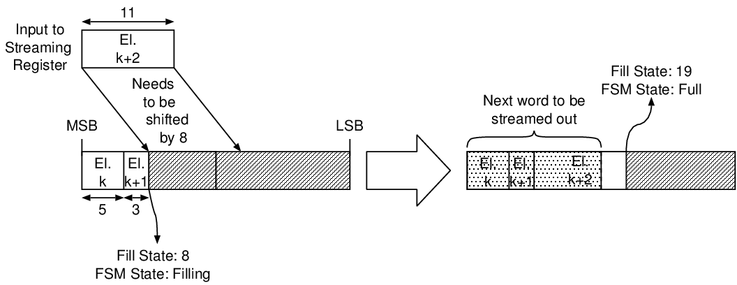
The variable-length nature of the encoding means that the hardware needs to concatenate words of variable lengths. This is achieved by using "streaming registers" and barrel shifters, which make up most of the logic resources the implementation takes up. A streaming register is a register of twice the word width of the streamed words. Variable-length data items are placed in the streaming register from the MSB downwards. If the streaming register is already partially filled, further items must thus be logically right-shifted in order not to overwrite with the contents already present. This process is illustrated 1. Once a streaming register is full, no more items can be added until the upper half is streamed out. At this point, the contents of the lower half must be left shifted by a word width (in the example, 16 bits).
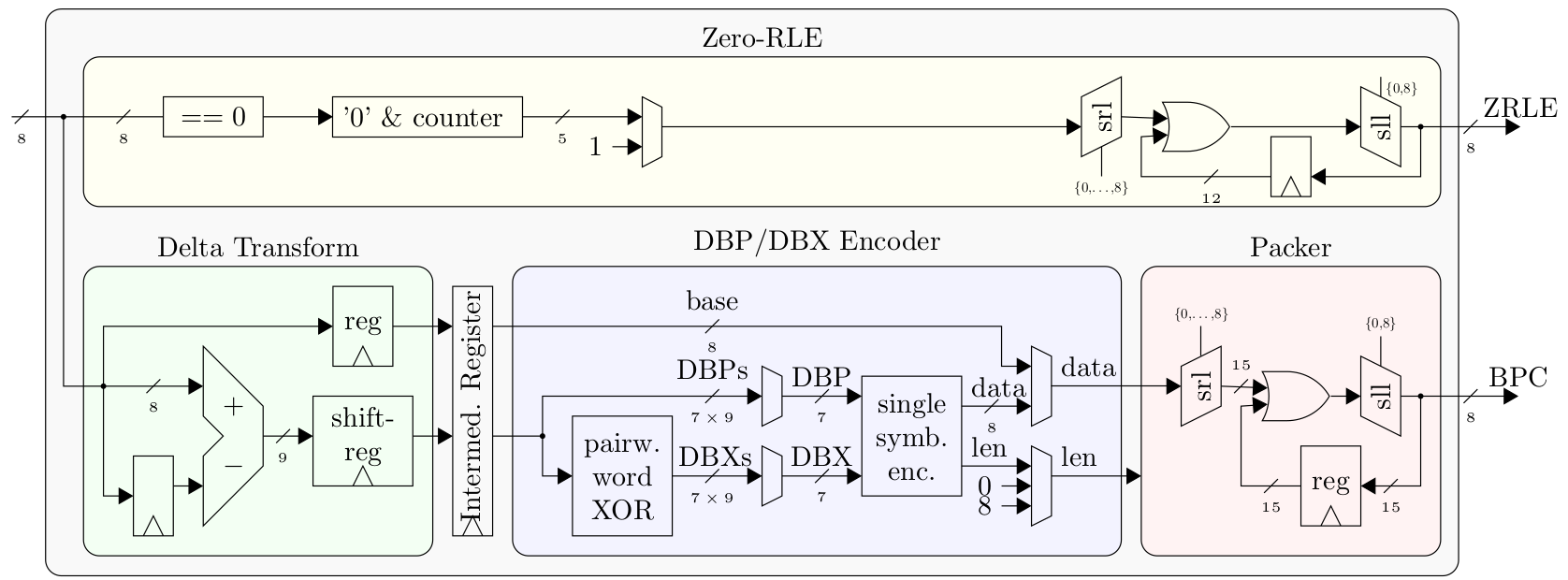
The encoder takes a stream of input words and outputs two streams:
- A BPC Stream of the encoded non-zero input words
- A ZNZ Stream of the zero runlength (ZRL) encoded zero/nonzero (ZNZ) stream
Along with the input words, the encoder takes a signal last_i
indicating whether the word that is currently being input is the last
word of a transmission. This will cause the encoder to flush the BPC and
ZRL encoders.
 The decoder is fundamentally a dual of the
encoder - it takes as its inputs the BPC and ZNZ streams produced by the
encoder and streams out the decoded words. To prevent outputting the
zero-padding added in the encoding process, it must also know the number
of unencoded words in the transmission.
Inputs and outputs are transmitted with valid/ready handshake interfaces, illustrated in the following figure. A transaction occurs on rising clock edge where the ready signal from the consumer and the valid signal from the producer are high. Generally, a producer is not allowed to deassert the valid signal before the corresponding transaction has been completed, i.e. before the consumer has asserted its valid signal. The word width of input words and output words is always equal.
All architecture parameters are defined in the src/ebpc_pkg.sv
file:
| Parameter | Function | Tested Values |
|---|---|---|
LOG_DATA_W |
log2ceil of the word width of the input/output data streams | 3, 4 |
BLOCK_SIZE |
Bit plane compression block size | 8, 16 |
LOG_MAX_WORDS |
log2ceil of the maximum number of uncompressed words in a single transmission | 24 |
LOG_MAX_ZRLE_LEN |
log2ceil of the maximum length of a zero runlength encoding block | 4 |
DATA_W=2^LOG_DATA_W>=BLOCK_SIZELOG_DATA_W>=3
- Stream in the data to be encoded with the
data_i,last_i,vld_i,rdy_ointerface. When the last word is transmitted, assertlast_i. - In parallel, read the output streams:
- ZNZ Stream:
znz_o,znz_vld_o,znz_rdy_i. - BPC Stream:
bpc_o,bpc_vld_o,bpc_rdy_i.
- ZNZ Stream:
- When
idle_ois asserted (afterlast_iwas asserted, i.e. input streaming has finished), output streaming has concluded and the next input transmission may begin.
The last word of the ZNZ stream will be zero-padded. The input to the internal BPC encoding block will be stuffed with zeros to a full block size, i.e. if the number of nonzero words in the input stream is not divisible by the block size, zero words will be inserted.
- Tell the block number of words to expect in the decoded
transmission:
num_words_i,num_words_vld_i,num_words_rdy_o. - Stream in the encoded words:
- ZNZ Stream:
znz_i,znz_last_i,znz_vld_i,znz_rdy_o. - BPC Stream:
bpc_i,bpc_last_i,bpc_vld_i,bpc_rdy_o. Use of theznz_last_iandbpc_last_isignals is optional, provided that the next data stream is not started before itsnum_words_ihandshake has been completed. In situations where the data streams and thenum_words_ihandshake are decoupled, they must be used. Otherwise, they may be tied to zero.
- ZNZ Stream:
- In parallel, read the decoded output stream:
data_o,vld_o,rdy_i,last_o.last_owill be asserted on the last output word. The next transmission may only be started afterlast_ohas been asserted.
BPC encoding is a variable-length encoding scheme and the encoded symbols are packed into words, so the encoded stream looks like this:
A conda environment YAML file is provided in the py folder. It
specifies all the python packages needed to simulate the designs with
cocotb, generate stimuli etc. To use it, you will need
Anaconda3/Miniconda3. From the py folder, type the following command
to create an environment called stream-ebpc:
conda env create -n stream-ebpc -f environment.ymlOur testbenches are written in Python using
cocotb. There are testbenches
supplied for 4 design entities in the tb folder:
bpc_encoder- this block performs bit-plane encoding on the input streamebpc_encoder- this top-level encoder block combines the BPC encoder and a zero runlength encoderbpc_decoder- this block decodes a stream of bit-plane encoded dataebpc_decoder- this top-level decoder block combines the BPC decoder block with a zero runlength decoder.
Makefiles are supplied for each testbench, along with wave view scripts
for Mentor Graphics QuestaSim. The makefiles set the cocotb environment
variable SIM_ARGS with QuestaSim-specific options, so for use with
another simulator they will have to be adjusted slightly. To step-debug
the testbenches with PyCharm, copy
the Pycharm debug egg (pydevd-pycharm.egg) to the tb folder,
uncomment the line in the Makefile augmenting the PYTHONPATH
environment variable and uncomment the lines in the testbench file that
look like this: #import pydevd_pycharm
#pydevd_pycharm.settrace('localhost', port=9100, stdoutToServer=True, stderrToServer=True) Follow the
guide
by JetBrains to set up remote debugging. You will need PyCharm
Professional for this to work.
The EBPC encoder testbench contains a (commented-out) test
(fmap_inputs) which can be used to automatically generate intermediate
feature maps of a variety of networks, as defined in the data.getModel
function and feed them to the compressor hardware. The python code uses
the popular PyTorch library. To run the tests,
you will have to download a dataset of your choice (e.g. the ImageNet
validation set). The code uses the TorchVision ImageFolder data
loader, which expects the images to be located in folders corresponding
to their labels. Thus, IMAGE_LOCATION in ebpc_encoder_tests.py needs
to be set to the parent folder containing only a subfolder which in turn
contains the images. Note that even just a single images produces
massive amounts of stimuli data, so only a fraction of the feature maps
are actually fed to the hardware (the fraction can be changed with the
FMAP_FRAC variable).
In the rtl_tb folder, there are file-based testbenches for the EBPC
encoder and decoder. Compilation and simulation scripts for Mentor
QuestaSim and Cadence IUS (unsupported) are included. To simulate the
designs using these file-based testbenches, you will need to perform 3
steps:
- Adapt the
CADENCE_IUSorQUESTA_VLOGandQUESTA_VSIMvariables in thecompile_sim_{design}.shscripts to your system - usually, the appropriate values arexrun,vlogandvsimrespectively. - Generate stimuli using the python script in the
py/stimuli_genfolder. It can be configured to generate feature map stimuli from various networks, using a configurable fraction of the feature maps (using all feature maps would result in excessive file sizes and simulation times). Edit the script to configure parameters such asBASE_STIM_DIRECTORY(where stimuli files are stored),NETS(which nets are used to extract feature map stimuli -randomandall_zerosare also valid options) etc. - configure the correct stimuli file paths in the
ebpc_encoder_tb.svandebpc_decoder_tb.svfiles in thertl_tbsubfolders.
If any issues arise, do not hesitate to contact us.
For information or in case of questions, write a mail to Georg Rutishauser. If you find a bug, don't hesitate to open a GitHub issue!


