Advanced Lane Finding Project
The goals / steps of this project are the following:
- Compute the camera calibration matrix and distortion coefficients given a set of chessboard images.
- Apply a distortion correction to raw images.
- Use color transforms, gradients, etc., to create a thresholded binary image.
- Apply a perspective transform to rectify binary image ("birds-eye view").
- Detect lane pixels and fit to find the lane boundary.
- Determine the curvature of the lane and vehicle position with respect to center.
- Warp the detected lane boundaries back onto the original image.
- Output visual display of the lane boundaries and numerical estimation of lane curvature and vehicle position.
I used the chessboard images in the 'camera_cal' directory to calibrate the camera. These images are various chessboard images taken from different angles.
First, I changed the image to grayscale and found the "image points" using OpenCV's findChessboardCorners() function. Assuming a board of size 9x6, I could not find the corner in some images, so I finally used the board sizes of [(9,6),(9,5),(6,5),(7,5)]
Next, I prepared "object points", which will be the (x,y,z) coordinates of the chessboard corners in the world. Because need to prepare different points according to board size, I defined a function called get_object_points().
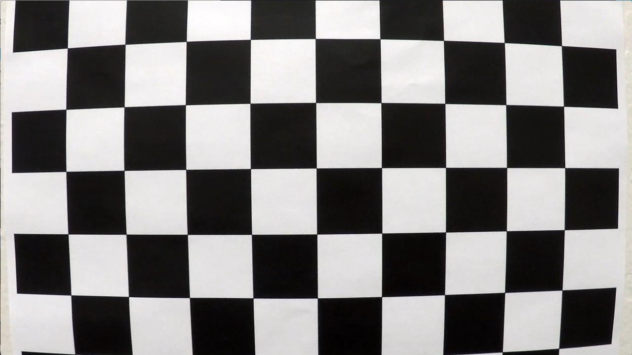
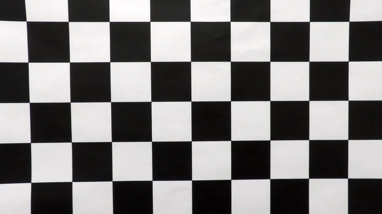
I then used the output objpoints and imgpoints to compute the camera calibration and distortion coefficients using the cv2.calibrateCamera() function. I applied this distortion correction to the test image using the cv2.undistort() function and obtained this result:
| Original | Undistorted |
|---|---|
 |
 |
Then I stored calculated matrices and distortion coefficients in the pickle file to calibrate other images taken with this camera later.
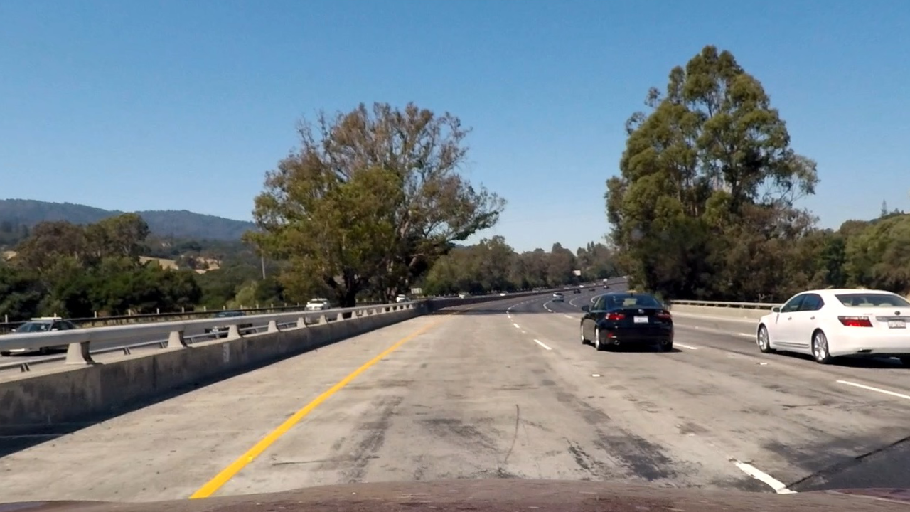
Using stored matrices and distortion coefficients in the pickle file, I can undistort the input image.
| Original | Undistorted |
|---|---|
 |
 |
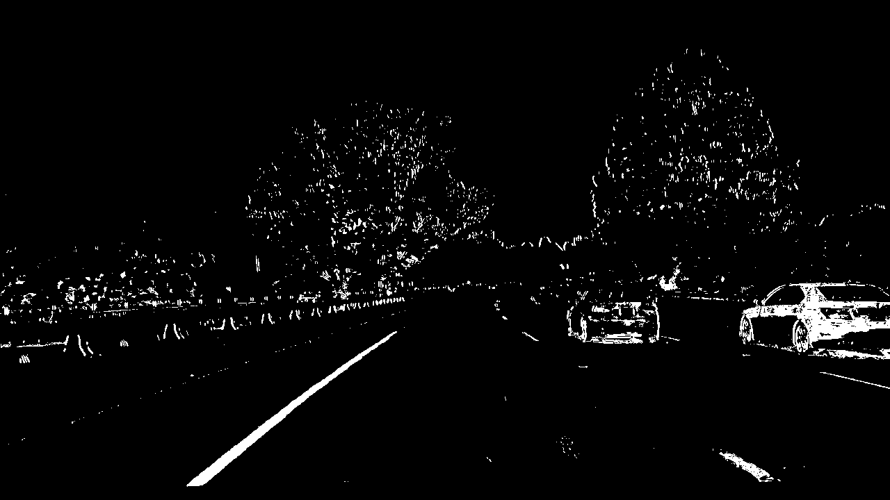
I used a various combinations of color and gradient thresholds to generate a binary image where the lane lines are clearly visible.
Apply the following filters:
- Takes an image, gradient orientation, and threshold min/max values
- Return the magnitude of the gradient for a given sobel kernel size and threshold values
- Return the direction of the gradient for a given sobel kernel size and threshold values
- Convert RGB to HLS and threshold to binary image using S channel
- Combine the above binary images to create the final binary image
Here's an example of my output for this step.
| Original | Thresholding |
|---|---|
 |
 |
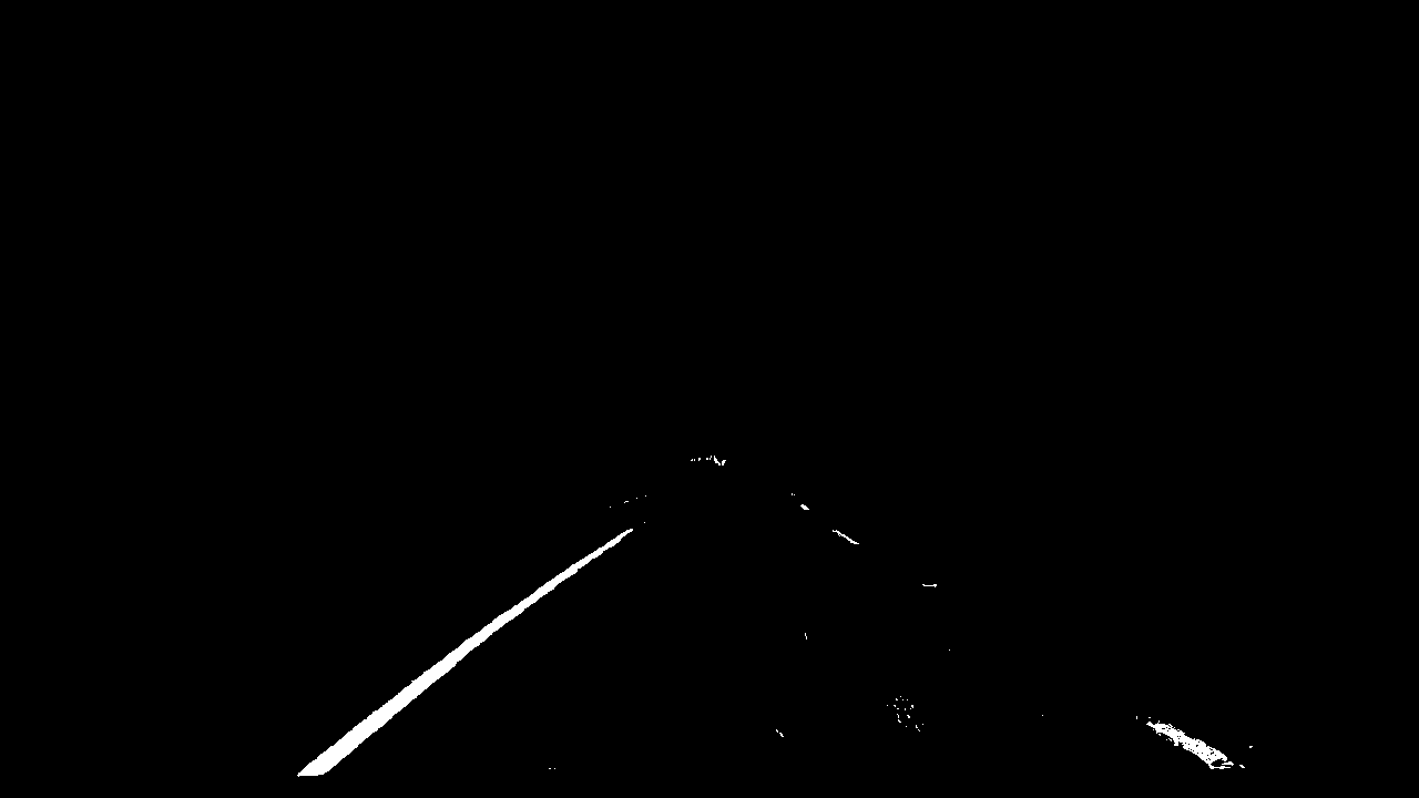
Only keeps the region of interest similar to project 1, the image defined by the polygon formed from vertices. The rest of the image is set to black.
| Thresholding | Region of interest |
|---|---|
 |
 |
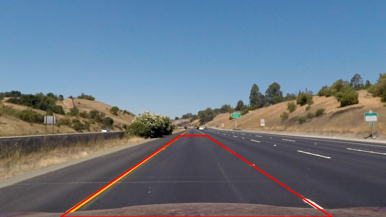
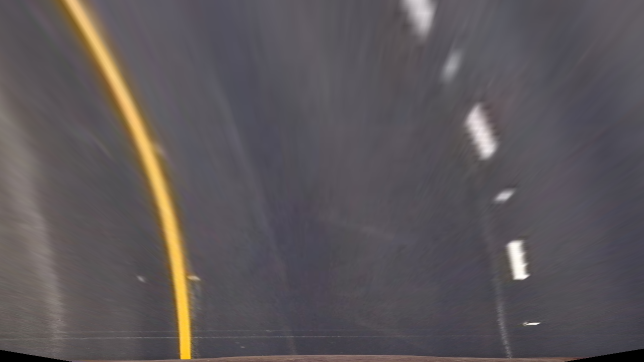
Next, I need to identify four source points for your perspective transform. The easiest way to do this is to investigate an image where the lane lines are straight, and find four points lying along the lines that, after perspective transform, make the lines look straight and vertical from a bird's eye view perspective.
This resulted in the following source and destination points:
| Source | Destination |
|---|---|
| 200,720 | 300,720 |
| 595,450 | 300,0 |
| 685,450 | 980,0 |
| 1100,720 | 980,720 |
I hard-coded the source and destination points for the perspective transform. To accomplish the perspective transform, I use OpenCV's getPerspectiveTransform() and warpPerspective() functions.
| Source points | Perspective Transform | Thresholding |
|---|---|---|
 |
 |
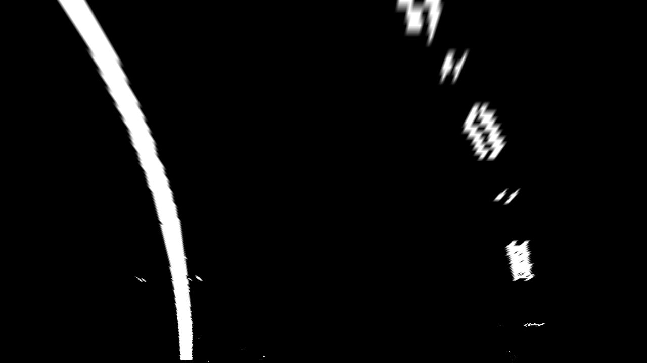 |
After applying calibration, thresholding, and a perspective transform to a road image, you should have a binary image where the lane lines stand out clearly. However, you still need to decide explicitly which pixels are part of the lines and which belong to the left line and which belong to the right line.
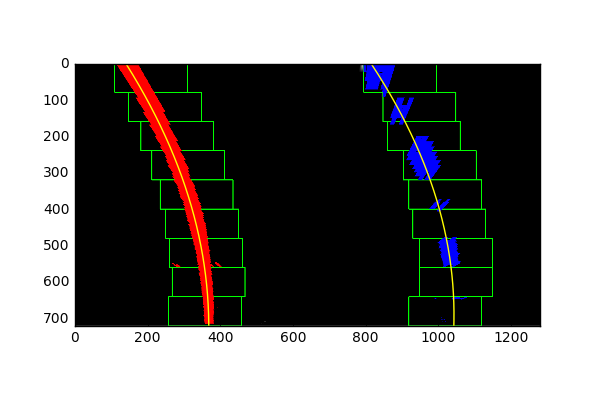
I implemented a sliding window in find_lines() function to find the lane pixels from the binary image. This function starts by taking a histogram of the binary image to find the two largest peaks. I use that as a starting point for where to search for the lines. From that point, I use a sliding window, placed around the line centers, to find and follow the lines up to the top of the image. Once I accurately find all of the lane pixels and separate them into the left and right lane lines, I was able to use the pixels to fit a polynomial to each lane.
Given the polynomial fit for the left and right lane lines, I calculated the radius of curvature for each line with get_curverad() function.
(awesome tutorial here)
But, I calculated the radius of curvature based on pixel values, so the radius we are reporting is in pixel space, which is not the same as real world space. So I also also converted the distance units from pixels to meters, assuming 30 meters per 720 pixels in the vertical direction, and 3.7 meters per 700 pixels in the horizontal direction.
Maybe camera is mounted at the center of the car. So, the lane center is assumed the midpoint at the bottom of the image between the two lines I've detected. The offset of the lane center from the center of the image (converted from pixels to meters) is car's distance from the center of the lane. See get_offset() function.
After I got a good measurement of the line positions in warped space, I draw the lines back down onto the road. At this time, the lane area is displayed in the original image, and information about the lane curvature and the vehicle offset is annotated.
The process is roughly as follows:
- Create a balnk image to draw the lines on
- Draw the lane onto the warped blank image
- Warp the blank back to original image space
- Combine the result with the original image
- Add text to the original image to display lane curvature and vehicle offset
The code to perform the above is in the function draw_lines().
Below is the final image with lane area drawn.
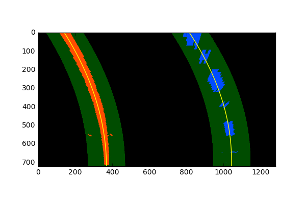
If the input was video, I could find the lane in a slightly better way. Once the line is found, in the next frame of video I don't need to do a blind search again, but instead I can just search in a margin around the previous line position like this:
To do this, I wrote the find_lines_by_previous() function.
I checked that endpoints of the lines are separated by approximately the right distance horizontally. Doing this I checked they are roughly parallel.
If my sanity checks reveal that the lane lines are problematic, I can simply assume it was a bad or difficult frame of video, retain the previous lines and step to the next frame to search again.
Even when everything is working, my line detections will jump around from frame to frame. To obtain a cleaner result, it can be preferable to smooth over the last n frames of video. So, I used the average of the five most recent measurements when displaying lanes in the image.
The code to perform the above is in Lanes class.
Here's a link to my video result
I think that the most important thing in this project is thresholding. It is very difficult to perform other subsequent tasks without accurately identifying the pixels in the lane. I've handled the given video moderately, but I think we need to test it in a variety of situations. It would be nice if there were images taken in various situations, such as different weather conditions, day and night, and various road surfaces. I've only implemented it with some of the techniques I've learned in my class, but I think more research is needed.
For the perspective transformation, I used a simple method to find four source points from the images of straight lines. However, this is possible because the road is assumed to be flat plane. Strictly speaking, this is not true, so I think it can be improved a little more.
Finally, I should check that the my detected lane lines makes sense. To confirm that my detected lane lines are real, I found the endpoints of lines and used the distance between the points. If I could inspect the lines in a better way, I think I could get better results.

