Download my bachalor's thesis.
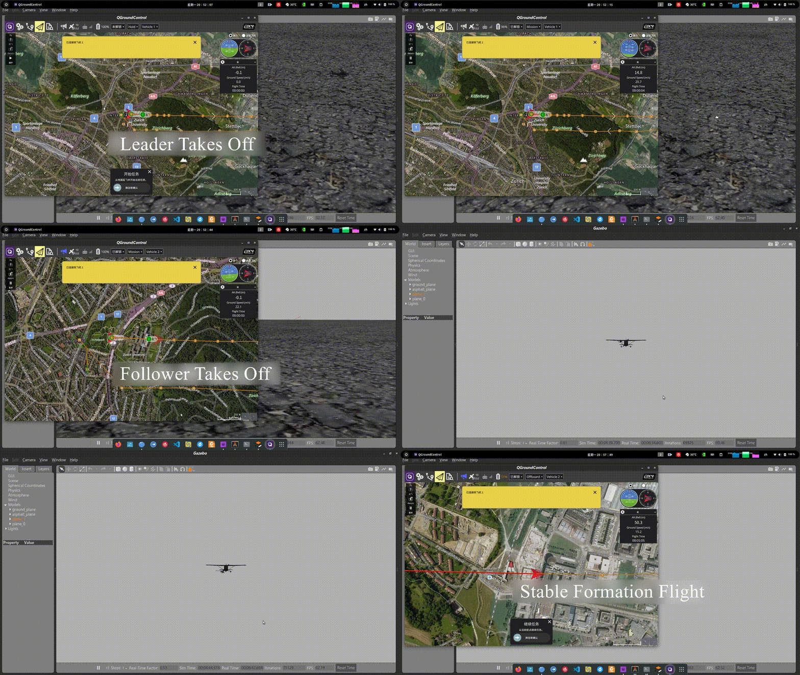
Flight Simulation based on Gazebo & ROS:
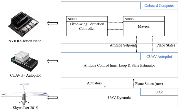
Use the “Leader-Follower” method to accomplish the 2 fixed-wing UAVs formation controlling.
- Earth
- No rotation, inertial coordinate system
- Flat, no curve
- Air
- No wind
- The air shares the same properties within the UAVs flight envelope.
- UAVs
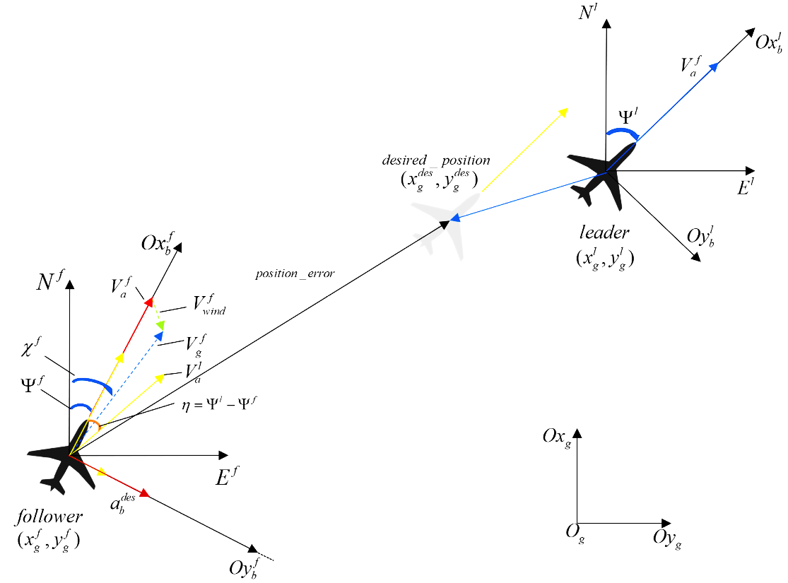
- Not sliding( sliding angle β=0), Coordinated Turn Model
- AOA(angle of attack) is small
- Rigid body
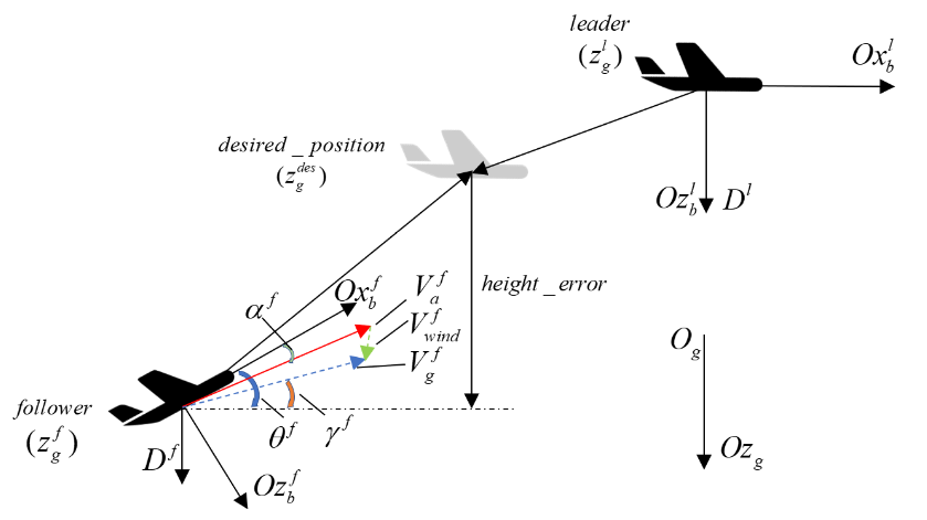
- Split this problem into horizontal plane and vertical plane!
- The formation control object:
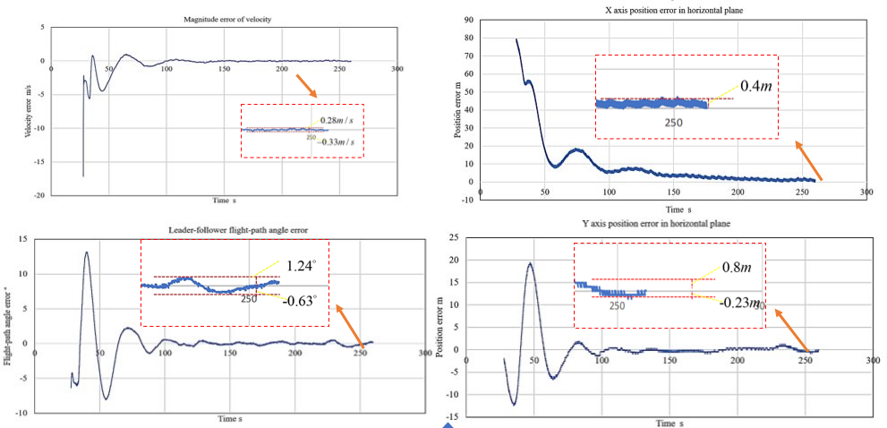
- Velocity of the follower is the same as the leader.
- Position error is zero
Note: no sliding angle, no wind and small AOA, velocity is (almost) along the body-fixed axis X.
- In the vertical plane, the most important error is the height error, which is also called the Z position error.
Note: We mainly focus on the horizonal plane motion. So, we won’t take it as a part of error in the vertical plane.
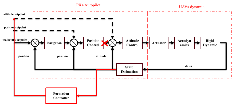
- Make use of the inner-loop controller, design the outer-loop!
- Input: the states of leader and follower.
- Output: the desired attitude setpoint and the throttle values of the follower.
- Why? Find the relationship between the errors and their corresponding controllable variables:
- X direction ==> velocity.
- Y direction ==> yaw rate.
- Z direction ==> height
- We want to eliminate both the position and velocity error at the same time!
- So, We define the linear combination of the position and velocity error as the “mixed error” along the X and Y axis in follower’s body-fixed coordinate system.
- We will use the height error as the error along the Z axis, treating the main motion as in the 2D plane.
Copyright (C) 2020 Aircraft Dynamics and Control Laboratory of BIT. All rights reserved.
