SDCND Term 3 Project 11: Path Planning
Path Planning Project for Udacity's Self-Driving Car Engineer Nanodegree Program
In this project, the goal is to design a path planner that is able to create smooth, safe paths for the car to follow along a 3 lane highway. The highway track has other vehicles, all going different speeds, but approximately obeying the 50 MPH speed limit. The path planner is able to keep inside its lane, avoid hitting other cars, and pass slower moving traffic all by using localization, sensor fusion, and map data.
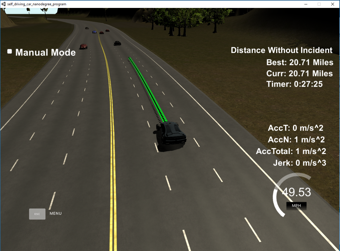
20+ miles is no problem:
 The results can be viewed here(Youtube):
Implementation
Various sensors (camera, radar, lidar) provide a self-driving car with continuous information about the environment, see here: Vehicle Detection. This information can be processed to answer important questions: Which objects are in the vicinity? How close are they? Do they behave statically or dynamically? What is their relative velocity and in which direction? And most importantly, where will these objects be during the near future (e.g. 5 seconds)? Furthermore it is possible to determine by localization where the vehicle is globally seen and targets can be defined, see here: Particle-Filter. If these questions are answered sufficiently exactly, a behavior planning can take place, which plans an action according to the situation, so e.g. lane change, braking, accelerating, lane holding. From these actions an executable trajectory has to be generated, which fulfills certain boundary conditions (maximum acceleration/jerk, etc.). This trajectory can then be sent to the controller, which transmits the commands to the real world, e.g. Model Predictive Control.
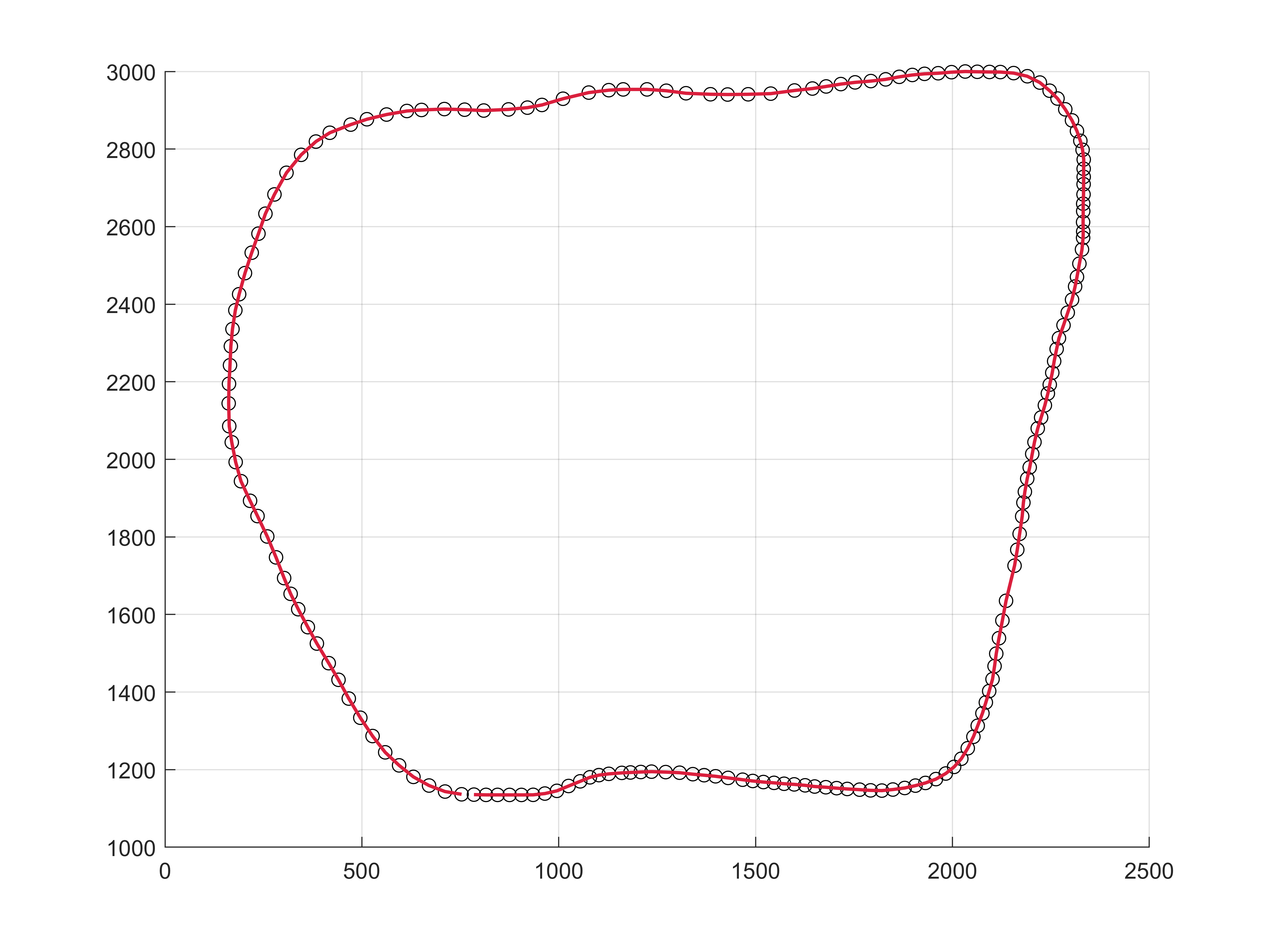
In this project a simulator is used to develop a path planner. The used highway track, which is characterized by the given waypoints looks like this in the global coordinate system (dots = waypoints):

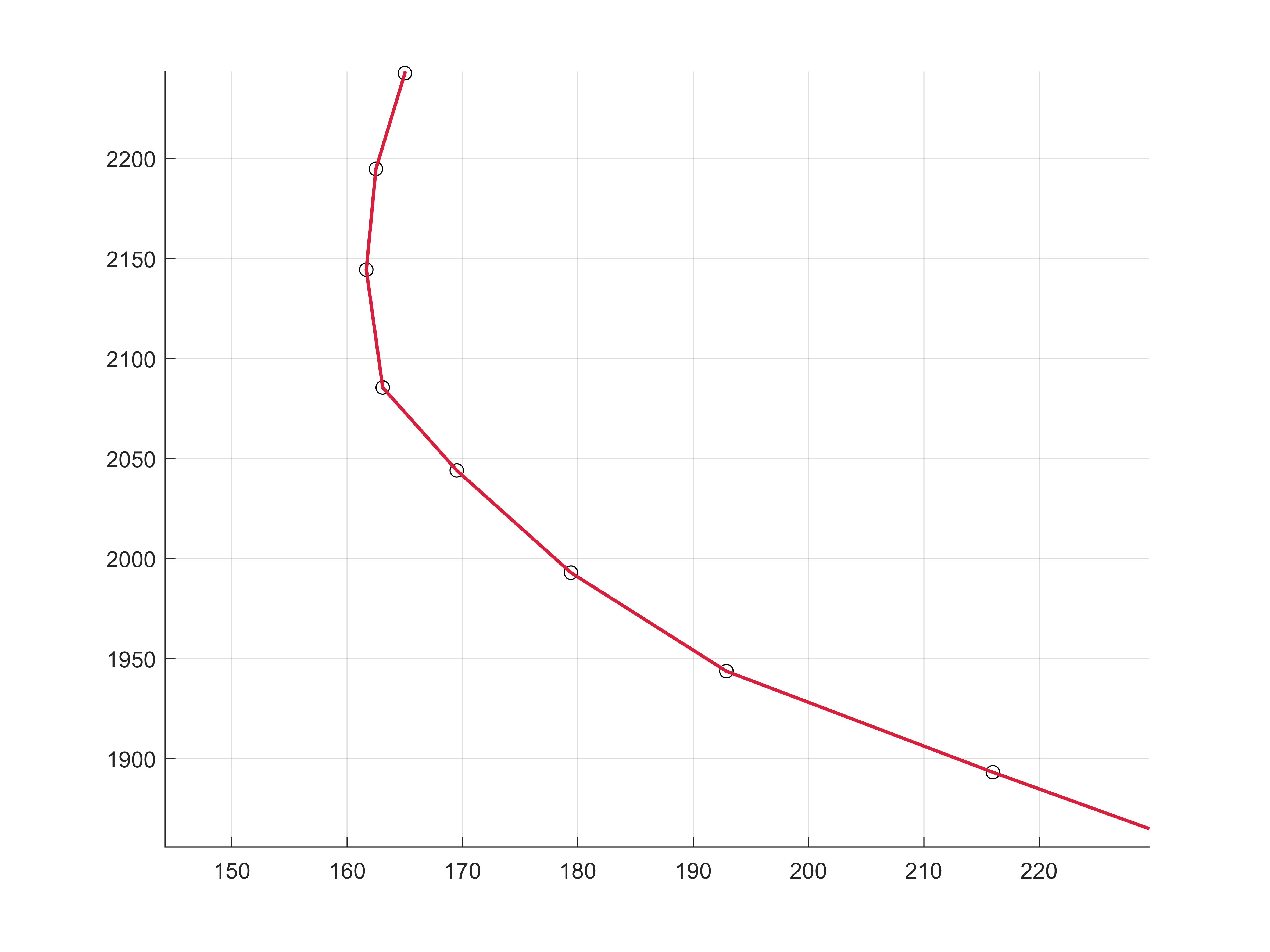
A closer look reveals that a linear interpolation between the sparse waypoints leads to sudden changes in direction and speed, so the limits of acceleration and jerk are broken.
 That's the reason why the included library spline.h is used (link) to smooth out the trajectories. Another option would be to use Jerk-Minimizing-Trajectories (JMT), but the use of spline interpolation gave sufficient results.
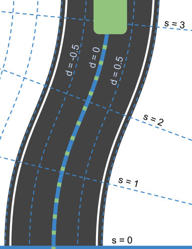
Another topic is the use of the frenet-coordinate system which is used extensively in this project. Reasons for doing this and how to do. Luckily helper code was provided to do the conversions from global to frenet coordinate system. This code is stored in utilities.cpp.
Sensor Fusion & Prediction line 113 to line 179
This part of the code takes the sensor fusion and ego car data and calculates signals, which are used in the following behavior planner, by predicting 50 timesteps * 0.02 seconds = 1 second into the future. These signals are
- danger - boolean, if the ego car and the checked car are less than 2.5m in the d-dimension and 9m in the s-dimension apart. This bit stops all unnecessary calculations and slows down the vehicle with the maximum deceleration.
- car_ahead - boolean, if the checked car is in the same lane and less than 30m in the s dimension away
- car_left - boolean, if the checked car is left to current ego car lane and 10m behind or 30m in front of the ego vehicle
- car_right - boolean, if the checked car is right to current ego car lane and 10m behind or 30m in front of the ego vehicle
- delta_s_left - double, minimum of all delta s of ego car and checked car on left lane
- delta_s_right - double, minimum of all delta s of ego car and checked car on right lane
- delta_s - double, minimum of all delta s of ego car and checked car on same lane
- ahead_speed - double, speed of the checked vehicle which as the minimum delta s on same lane
Behavior Planning line 178 to line 228
The signals determined previously are now used to plan the behavior of the vehicle and enable a generation of the trajectory in the next step. Here two important question have to be answered:
- Change lane or keep lane?
- Positive or negative acceleration?
The signals that result from this are the following:
ref_vel - double, value of velocity lane_change_left_best_opt - boolean, if left lane is best option follow_car_ahead - boolean, if there is a car in the same lane and it is not safe to change lanes and a matching of ego car velocity is needed planned_lane - integer, planned lane number. 0 = left, 1 = middle, 2 = right
Trajectory Generation line 229 to line 341
In this part a Jerk-Minimizing-Trajectory (JMT) could be used, but the Udacity seed project suggested using the spline.h library helps out a lot. Futhermore the Q&A from Udacity regarding this project was helpful to create smooth trajectories.
The code calculates the trajectory based on the speed and lane output from behavioral planning, vehicle coordinates and past waypoints.
Two types of vectors are used here, one is the "food" for the spline (ptsx, ptsy), the other is the result of the trajectory generation and outputs a series of global x,y points (next_x_vals, next_y_vals) for the simulation.
First, a certain number (use_no_old_points) of points of the last trajectory (or the current vehicle position, if there is no previous trajectory) is placed in the vector for the global points. This number is variable to allow fast course changes in critical situations (e.g. danger, follow_car_ahead).
Then the last two points are also inserted into the spline-food-vectors. Afterwards a number of waypoints at a defined distance will be inserted in these vectors. These vectors of points are now converted into the local coordinate system of the vehicle (displacement and rotation) in order to simplify the following calculations. The necessary functions for this can be found in utilities.cpp. With these points the spline will be initialized.
Now new local points are created with the help of the spline by evaluating the spline at selected x-points. The x-distance of these points is achieved by integrating the velocity and cumulating this result, i.e. the velocity of each trajectory is constant. The coordinates are then converted from local coordinates to global coordinates and passed to the simulation.
Dependencies
- cmake >= 3.5
- make >= 4.1
- gcc/g++ >= 5.4
- Udacity's simulator
Setup and Running
These are the suggested steps for Windows setup:
- Follow these instructions for setting up Ubuntu BASH.
- Download Windows simulator here.
- Open Ubuntu Bash (write following commands to Ubuntu Bash command window)
sudo apt-get updatesudo apt-get install gitsudo apt-get install cmakesudo apt-get install opensslsudo apt-get install libssl-dev- navigate to where you want to clone this repository to, for example:
cd /mnt/c/Users/Bob git clone https://github.com/autonomobil/SDCND-P11_Path-Planning-Project- navigate to project folder:
cd SDCND-P11_Path-Planning-Project sudo rm /usr/lib/libuWS.so./install-ubuntu.sh- navigate to the build folder:
cd build - Execute
cmake .. && make - Launch the term3_sim.exe from Windows simulator folder
- Execute
./path_planning - If you see
Listening to port 4567 Connected!!!, it is working - Press Select


