- Author: Richard James Howe
- License: 0BSD / Public Domain
- Email: mailto:howe.r.j.89@gmail.com
- Repo: https://github.com/howerj/lfsr-vhdl
This project contains a CPU written in VHDL for an FPGA using a Linear Feedback Shift Register (LFSR) instead of a Program Counter, this was sometimes done to save space as a LFSR requires fewer gates than an adder, however on an FPGA it will make very little difference as the units that make an FPGA (Slices/Configurable Logic Blocks) have carry chains in them. The saving would perhaps be more apparent if making the system out of 7400 series ICs, or if laying transistors out by hand.
See https://github.com/howerj/lfsr for more information.
The system contains a fully working Forth interpreter.
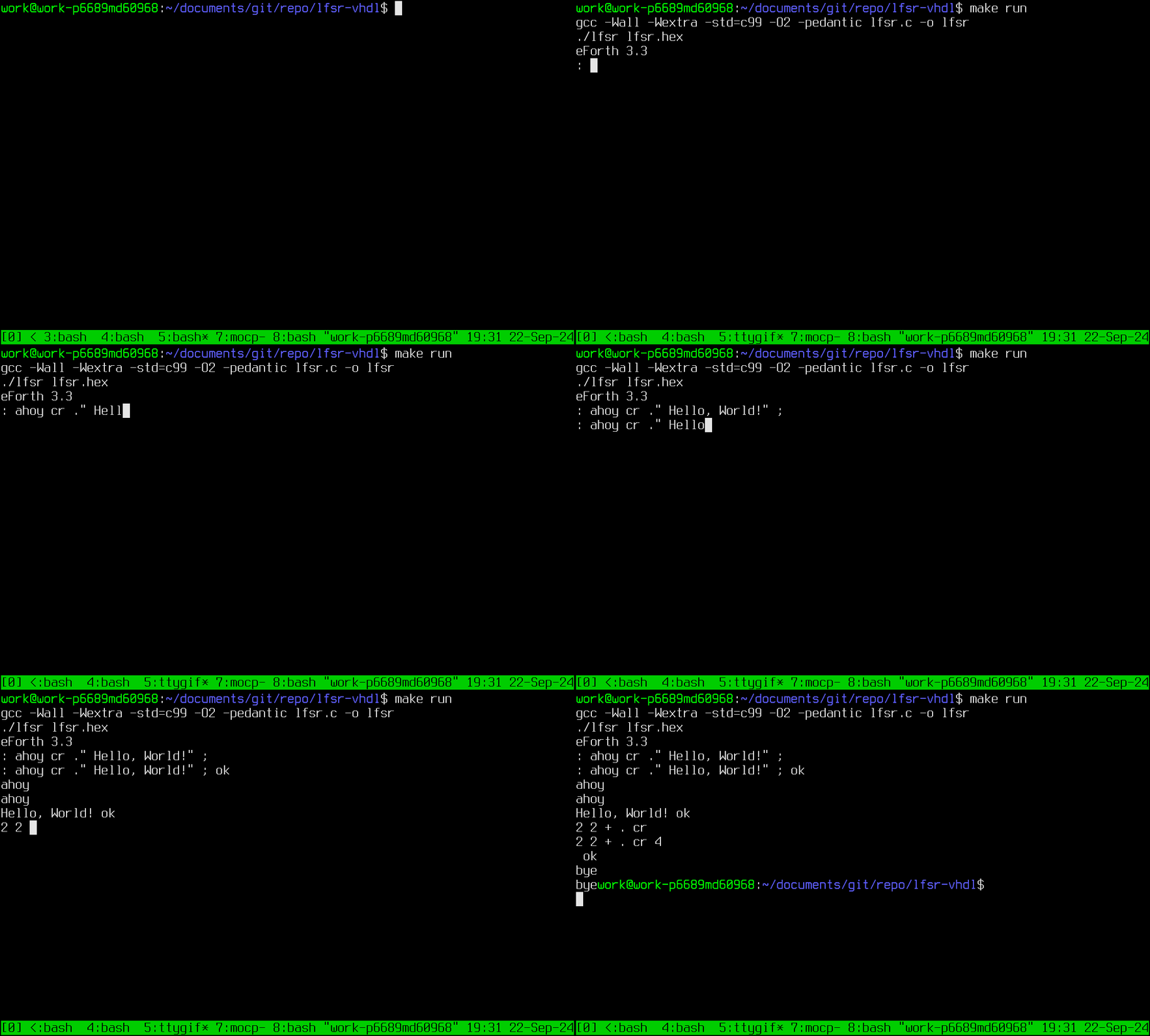
The project currently works in simulation (it outputs the startup message "eForth 3.3" with a new line) and accepts input (try typing "words" when the simulation in GHDL is running).
Here is an example session of the simulator running:
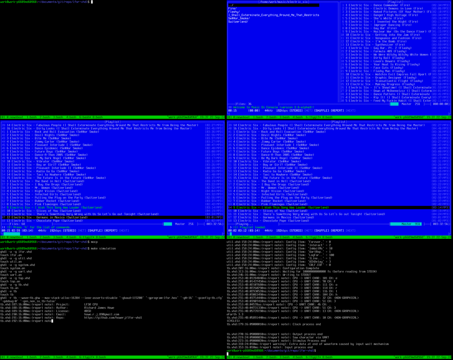
And the VHDL running under GHDL for a limited number of cycles:
The system runs can run at 151.768MHz (on a Spartan-6) according to the timing
report. The CPU itself is quite small, here is a cut-down report on the
resources consumed for commit 7dc4c9b7e03082364b09540bb2d97105d2858d0b:
+------------------------------------------------------------+
| Module     | Slices | Slice Reg | LUTs  | BRAM/FIFO | BUFG |
+------------------------------------------------------------+
| top/       | 3/53   | 9/105     | 1/151 | 0/8       | 1/1  |
| +system    | 0/27   | 0/47      | 0/85  | 0/8       | 0/0  |
| ++bram     | 0/0    | 0/0       | 0/0   | 8/8       | 0/0  |
| ++cpu      | 27/27  | 47/47     | 85/85 | 0/0       | 0/0  |
| +uart_rx_0 | 12/12  | 24/24     | 39/39 | 0/0       | 0/0  |
| +uart_tx_0 | 11/11  | 25/25     | 26/26 | 0/0       | 0/0  |
+------------------------------------------------------------+
No LUTRAM/BUFIO/DSP48A1/BUFR/DCM/PLL_ADV used
The above is indicative only as the actual resources used may vary from commit to commit, but also because of the tool chain and FPGA targeted.
Even given that though it is clear that this system is small. The CPU only occupies 27 slices, which is only a little larger than the bit-serial CPU available at https://github.com/howerj/bit-serial, and this 16-bit CPU is much faster.
To build you will need make. To make the C Virtual Machine you will need a C
compiler of your choosing.
To run the C VM type:
make run
You should be greeted by the message eforth 3.3. Type bye and hit ENTER
to quit (CTRL-D will not work, this is not a bug). Type words for a list of
defined Forth words. An example session:
: ahoy cr ." GOODBYE, CRUEL WORLD!" cr ;
ahoy
2 2 + . cr
bye
This is not a Forth tutorial. For a Forth tutorial look elsewhere. Try "the internet". I am sure they have something.
Making the simulation requires GHDL:
make simulation
There is a configuration file for the simulation in the file tb.cfg that
allows changing many test bench parameters without recompiling the test bench.
GHDL also allows you to set generics via the command line, which is done in the
makefile. For example make simulation DEBUG=2 sets the top level debug
generic to 2, bear in mind when changing the generics in tb.vhd that the
makefile can override these constants!
To build for an FPGA you will need Xilinx ISE 14.7:
make synthesis implementation bitfile
The system has not been tested on an FPGA at the moment. If you have any luck, let me know.
A short summary of the instruction set and design:
- The machine is an accumulator based machine.
- All instructions are 16-bits in length.
- The top four bits determine the instruction.
- The lowest four bits are the operand parameter.
- Addresses are in number of 16-bit cells, not bytes.
- The program counter is 8-bits in size and is advanced with a LFSR.
- The top most bit determined whether the operand is used directly or whether or it loaded first.
The instruction set has been carefully chosen so that it should be very simple to implement in a traditional manner, or in a bit-serial fashion (much like my other CPU project at https://github.com/howerj/bit-serial that runs on an FPGA). It has also been designed so that it should be possible to implement in 7400 series logic ICs (excluding ROM and RAM) as well as on an FPGA. There may be no savings in logic on an FPGA due to the fact that slices have a built in carry chain (usually), but a comparison could be made when the system is implemented on an FPGA (This has been done, there is very little difference).
As the Program Counter does not use addition, it was decided that addition should be removed from the instruction set. It would be a bit weird to worry about all the gates the Program Counter is using and then just include an adder elsewhere. The ADD instruction is sorely missed and makes the Forth code more complex and slows it down. The only other instruction that feels like it should be present (to me) is bit-wise OR, in practice it is not used that much within the interpreter so it not missed, it is reimplemented using bitwise AND and INVERT (XOR against all bits set).
The instruction layout is:
+----------+---------------+-------------------+
|  BIT 15  | BITS 12 to 14 |    BITS 0 to 11   |
+----------+---------------+-------------------+
| INDIRECT | INSTRUCTION   | VALUE   / ADDRESS |
+----------+---------------+-------------------+
The INDIRECT flag determined whether bits 0 to 11 are treated as
a value (not set) or an address (INDIRECT is set).
The INSTRUCTION field is 3-bits in size, the instructions are:
0 : XOR   : ACC = ACC ^ ARG
1 : AND   : ACC = ACC & ARG
2 : LLS1  : ACC = ARG << 1
3 : LRS1  : ACC = ARG >> 1
4 : LOAD  : ACC = MEM[ARG]
5 : STORE : MEM[ARG] = ACC
6 : JUMP  : PC = ARG
7 : JUMPZ : IF (ACC == 0) { PC = ARG }
All instructions advance the program counter except JUMP, and
(conditionally) JUMPZ. All instruction affect or use the accumulator
except the jump instructions. MEM consists of a linear array of
16-bit values.
There is one special address, address 0. This address is never
incremented after an instruction is run as this is a lock up state for
the LFSR, the current instruction will be executed indefinitely. A way
to exit this condition is for the first instruction to be a jump to
address 1, however any non-zero address will do. The system starts
up executing from address zero. Conditional jumps could be used to
determine whether to reset or halt the system if needed. Alternatively
a LFSR that used XNOR could have been used (the lockup state for which
is all ones) but it was not.
ACC is the 16-bit accumulator.
ARG is either the zero extended 12-bit operand (the lowest 12-bits
of the instruction) as is, or the 16-bit value MEM[operand] if the
topmost bit of the instruction is set.
Input and Output is memory mapped, reading from a negative address (high bit set) causes a byte to be read or output. This is triggered from reading or writing to any negative address, if multiple peripherals are to be added the address will have to be decoded correctly.
For the purposes of simulation JUMP will cause the CPU to halt if
the jump address is the same as the program counter. This will not
be implemented in hardware.
The program counter uses a 8-bit LFSR to advance, that means only 256 16-bit values can be directly addressed by this CPU, this is not a limitation that matters for the purpose of the software running on this system, a complete Forth Programming Language image, as the Virtual Machine that supports Forth can be written in under 256 instructions for this system. That Forth Virtual Machine can address more memory by using LOAD/STORE to access values outside the 256 instruction range.
This instruction set might change depending on the implementation, or when it comes to implementation, to make things easier and smaller still.
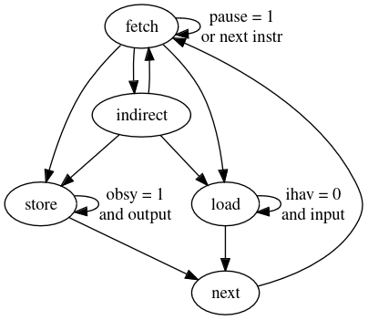
The following can be used to create a state-machine diagram with Graphviz, this can be done online, see https://dreampuf.github.io/GraphvizOnline/:
digraph LfsrCpu {
	fetch -> fetch [label = "pause = 1\nor next instr"];
	fetch -> indirect;
	fetch -> load;
	fetch -> store;
	indirect -> fetch;
	indirect -> load;
	indirect -> store;
	load -> load [label = "ihav = 0\nand input"];
	load -> next;
	store -> next;
	store -> store [label = "obsy = 1\nand output"];
	next -> fetch;
}
Alternatively, here is a veritable feast of a PNG file for both your lovely eye balls to take in and gaze upon with wonder, or to just look at, whatever:
Edit tb.cfg and ensure that the number of clocks to run for is over 90000000 (or equal
to), and that we are running in interactive mode, the following configuration
file should work:
Clocks.. # Number of clock cycles to run for
90000000
Forever. # If greater than zero run forever
0
Interact # Is this session interactive?
2
InWaitMs # Time to wait before getting user input
10
UartRep. # UART reporting level, if non zero `report` UART chars
1
LogFor.. # Extra debug logging for this many cycles
100
1Line... # Exit after getting one line of input if non zero
1
UChDelay # Delay (ms) between sending UART characters
1
CRLF.EOF # Line ending CRLF (1) or LF (0)?
0
Then run the command:
echo "bye" | make simulation DEBUG=2 > vhdl.txt
And then:
echo "bye" | DEBUG=1 ./lfsr lfsr.hex 2> c.txt
And compare with:
vimdiff vhdl.txt c.txt
You will notice differences, however they should be minor, obvious, and mostly related to VHDL report messages. The instructions executed should be identical so long as the input is identical, to make sure this is the case the line endings also need to be made to be identical for both inputs.
Empirically the system averages 2.4 clock cycles (or 2.4 state changes) to execute a single instruction, this was measured by executing the default Forth image and feeding it a line of text with the quit/halt word "bye" in it. This was calculated from the following table, which contains the number of times the instruction has been encountered, whether the instruction is the indirect variant (marked with an 'i'), the instruction, the number of cycles needed to execute that instruction and the cycles multiplied by instruction cycle length.
+--------+--------+----------+---------+---------+
| cycles | indir? | instr?   | cyc/ins |         |
+--------+--------+----------+---------+---------+
| 369492 |        |  a_jmp   | 1       | 369492  |
| 241070 |        |  a_jmpz  | 1       | 241070  |
| 880098 |        |  a_load  | 3       | 2640294 |
| 1450   |        |  a_lsr1  | 1       | 1450    |
| 880388 |        |  a_store | 3       | 2641164 |
| 206102 | i      |  a_and   | 2       | 412204  |
| 65755  | i      |  a_jmp   | 2       | 131510  |
| 32042  | i      |  a_jmpz  | 2       | 64084   |
| 53057  | i      |  a_load  | 4       | 212228  |
| 173287 | i      |  a_lsl1  | 2       | 346574  |
| 17053  | i      |  a_store | 4       | 68212   |
| 173513 | i      |  a_xor   | 2       | 347026  |
+--------+--------+----------+---------+---------+
Total Instructions executed: 3093307
Total Instruction cycles: 7475308
- Improve the documentation; the addition of timing diagrams, terminal capture of the simulation running, state-machine diagrams and the like would all help. Much of the documentation from the sister project could be incorporated into this one.
- Optimize the CPU core:
- The Input/Output system could be reworked, making I/O truly memory mapped.
- See https://github.com/howerj/lfsr for more information and suggestions.
- The number of these devices that could fit on one device could be quite
large, limited perhaps by the number of Block RAMs available. Modifications
would have to be made to program and interact with a matrix of these CPUs,
but it might be a neat thing to do. They could take their input from the same
UART and the same starting commands or boot image, synchronization could be
partially achieved with
pause,ihavandobsysignals. Each CPU would need an identifier assigned to it. It might be a good idea to have a way for each CPU to talk to its immediate neighbors. Most of these problems could be solved with a adjustments to the I/O system and the addition of peripherals and pseudo peripherals. - The
lfsr.vhdfile is quite configurable with many generics, the tool-chain could be made to generate Forth images that deal with the variants. - A Dual-Port version of the CPU would be faster, although require more resources, this CPU in its current form can share one half a Dual Port Block RAM allowing very fast memory mapped I/O.
- The eForth image could be turned into ROM sections (the Forth Virtual Machine and the initial Forth dictionary could go here) and sections that can be stored in RAM. This ROM/RAM version would also execute faster, provided only the Forth VM was to be stored in ROM.
- A bit-serial version of this CPU could be made, it might be smaller, it would certainly be slower.
- A simulation written in VHDL using components based off of real 7400 series devices could be made. This should make it easier to build a physical version of this system out of 7400 series ICs, and will most likely be faster than other digital simulators. This would involve making components for each 7400 series IC we would want to use, sticking to the common ones (NAND gates, counters, multiplexors, flip flops, comparators, decoders) would be best, as some of the more exotic devices (such as ALUs, adders, ...) can be harder to find.
- The article https://www.fpgarelated.com/showarticle/797.php, or Inside the Spartan-6: Using LUTs to optimize circuits by Victor Yurkovsky, publish June 24, 2015, contains information about optimizing LUT usage by explicitly instantiating and placing LUTs and other FPGA logic. If we really want to shrink this system, we could do the same here. There is also an interesting article about outputting VGA signals in only 7 slices: https://www.fpgarelated.com/showarticle/42.php.
- The instruction set could be played around with, there are some really
interesting instructions such as
execute this register as an instruction(which is appropriate for a register machine and not an accumulator machine, adding a full rotate and removing the shift left/right by one instructions, or perhaps my favorite, using a Lookup Table (LUT) to determine what the output should be for two inputs which would allow all two input logic gates to be implemented, see https://arnaud-carre.github.io/2024-10-06-vpternlogd/ for an example of a three input version. Setting the LUT would require setting a 4-bit register for a 2-input LUT, which could be tacked on to the JUMP instruction as we have bits to spare (we only use 8-bits).
- https://github.com/howerj/lfsr
- https://github.com/howerj/subleq
- https://github.com/howerj/bit-serial
- https://github.com/howerj/7400
- https://github.com/howerj/subleq-vhdl
- https://www.amazon.com/SUBLEQ-EFORTH-Forth-Metacompilation-Machine-ebook/dp/B0B5VZWXPL
- http://ghdl.free.fr/
- https://www.righto.com/2020/11/reverse-engineering-ram-storage-in.html
- https://sheep-thrills.net/NES_lockout_chip_address_smartness.html
- https://en.wikipedia.org/wiki/Texas_Instruments_TMS1000
- https://hackmii.com/2010/01/the-weird-and-wonderful-cic/


