----- ms-van3t is pronounced "em-es vanet"
ns-3 modules to build and simulate ETSI-compliant VANET (V2X) applications using SUMO (v-1.6.0+) and ns-3 (ns-3-dev, version supporting the NR-V2X module by CTTC), with the possibility of easily switching stack and communication technology.
It has been tested with SUMO v1.6.0, v1.7.0, v1.8.0, v1.12.0, v1.18.0 on Ubuntu 20.04 and 22.04. Back compatibility is not ensured with new versions of TraCI.
To build the project:
-
Install SUMO following the guide at https://sumo.dlr.de/wiki/Downloads
-
You can use
sudo add-apt-repository ppa:sumo/stable
sudo apt update
sudo apt install sumo sumo-tools sumo-doc -
Be careful: in the future the previous commands will install updated version of SUMO which are not ensured to work with this scripts (that are tested with any version from v-1.6.0 to v-1.18.0 )
-
Test sumo by opening a terminal and running "sumo-gui".
-
Possible problems:
  You may get the following error when running SUMO:

  "sumo-gui: symbol lookup error: /usr/lib/libgdal.so.26: undefined symbol: GEOSMakeValid_r"

  To solve it, remove all the reference to GEOS inside /usr/local/lib/ (do NOT do it if you need the GEOS library):

  "sudo rm /usr/local/lib/libgeos*"
-
-
Clone this repository in your pc:
git clone https://github.com/ms-van3t-devs/ms-van3t.git
- Run, from this repository either:
./sandbox_builder.sh install-dependencies -> if this is the first time you install ns-3 or ms-van3t on your system
or
./sandbox_builder.sh -> if this is not the first time you install ns-3
This script will download the proper version of ns-3-dev and install this framework. The folder ns-3-dev will remain linked to this GitHub repository (not to the vanilla ns-3-dev one), allowing you to more easily develop updates and possibile contributions to ms-van3t.
-
Configure
ns3to build the framework with<ns3-folder>./ns3 configure --build-profile=optimized --enable-examples --enable-tests --disable-python (add here what you want to enable)"- The usage of the optimized profile allows to speed up the simulation time. This command should be launched from inside thens-3-devfolder. -
Important: If you are compiling ms-van3t on Ubuntu 22.04 LTS or later, you need to specify, when calling
./ns3 configure, also the--disable-werrorflag -
Build ns3:
./ns3 build
Important
src/automotive/ contains all the application related files and all the source code implementing the ETSI ITS-G5 stack for vehicular communications. Inside sumo_files_v2v_map you can find the SUMO map and trace for the V2V sample application, while inside sumo_files_v2i_map you can find the SUMO map and trace for the V2I sample application. Similarly you can find the SUMO map and trace for the Traffic Manager sample application inside sumo_files_v2i_TM_map and the ones for the Emergency Vehicle Warning inside sumo_files_v2i_EVW_map
src/traci/ and src/traci-applications/ contain instead all the logic to link ns-3 and SUMO.
src/cv2x/ contains the model for C-V2X in transmission mode 4.
The user is also encouraged to use the sumo_files_v2v_map and sumo_files_v2i_map folders to save there the SUMO-related files for his/her own applications.
The version of CAM and DENM messages (v1 or v2) can be easily switched by relying on the switch_ETSI_version.sh script. This script relies on the ns-3-dev/src/automotive/model/ASN1/currmode.txt file. Please never modify it manually or delete it!
In addition to SUMO and GPS traces ms-van3t supports the use of CARLA for mobility and sensor perception simulation. This extension leverages the OpenCDA framework to develop an LDM module and extend the gRPC adapter devised here to be able to extract not only localization information from CARLA but also perception information from the LDM module. The developed client module on ns-3 queries the information to use it for the mobility of each of the ns-3 simulated nodes and to update the LDM module with all perception data sent over the simulated vehicular network.
System requirements
We highly recommend running ms-van3t-CARLA on Ubuntu 20.04 (used for developing the framework) or Ubuntu 18.04, Ubuntu 22.04 is not officially supported by CARLA. If both CARLA and OpenCDA need to be installed we recommend at least 35GB of free space on your system. For smooth execution of simulation (especially if AI/ML models are leveraged for the perception simulation) we recommend using a GPU with at least 8GB of memory. The version of CARLA supported by ms-van3t-CARLA is CARLA 0.9.12.
Installing ms-van3t-CARLA
To enable ms-van3t-CARLA, after following the steps detailed above to build the project, from inside the ns-3-dev folder execute the switch_ms-van3t-CARLA.sh script.
The script will try to find the path of your CARLA and OpenCDA installation to be defined in the CARLA-OpenCDA.conf file. If the user already has an installation of either CARLA or OpenCDA they should specify the path to the installation together with the path to their Python environment in the following way:
CARLA_HOME=/path/to/CARLA_0.9.12
OpenCDA_HOME=/path/to/OpenCDA
Python_Interpreter=/path/to/anaconda3/envs/msvan3t_carla/bin/python3 if using conda or Python_Interpreter=python3.7 otherwise.
In case this is the first time using either CARLA or OpenCDA the script will install them prompting for confirmation in each case. It is highly recommended to install OpenCDA with conda.
Once the script finishes its execution the user should build the project again with ./ns3 build.
ms-van3t-CARLA examples
Two examples leveraging CARLA are provided, showcasing how to use the extension with both IEEE 802.11p and NR-V2X as access technologies. To run the provided examples:
./ns3 run "v2v-carla-80211p" or ./ns3 run "v2v-carla-nrv2x"
For further description of the modules provided in this extension please refer to our paper here.
Although not necessarily required, you can also configure an IDE in order to more comfortably work with ms-van3t. The suggested IDEs, which has also been used for the development of ms-van3t, are QtCreator and CLion.
You can find all the instructions for setting up QtCreator with ns-3 (and the same applies to ms-van3t, as it is based on ns-3) on the official ns-3 Wiki.
QtCreator can be installed on Debian/Ubuntu with:
sudo apt install qtcreator
You need also to install the libclang-common-8-dev package (the command for Debian/Ubuntu is reported below):
sudo apt install libclang-common-8-dev
Not installing libclang-common-8-dev may result in QtCreator wrongly highlighting several errors and not recognizing some types, when opening any source or header file, even if the code compiles correctly.
Important: if libclang-common-8-dev is not available, you can try installing a newer version. For example, on Ubuntu 22, we verified that libclang-common-15-dev works well too.
CLion can be easily installed with the JetBrains Toolbox App.
You can find all the instructions for setting up CLion with ns-3 (and the same applies to ms-van3t, as it is based on ns-3) on our documentation.
ms-van3t currently supports the following ETSI C-ITS messages:
- CAM
- DENM
- IVIM
- CPM
- VAM
For the transmission and reception of IVIMs (from an RSU to vehicles), you can refer to the v2i-emergencyVehicleWarning-80211p example.
ms-van3t currently supports two stacks/communication technologies for V2I/V2N:
- 802.11p, communicating, for instance, with a Road Side Unit (sample program name:
v2i-areaSpeedAdvisor-80211p) - LTE, for V2N communications (sample program name:
v2i-areaSpeedAdvisor-lte)
To run the sample V2I program you can use:
./ns3 run "v2i-areaSpeedAdvisor-lte" or
./ns3 run "v2i-areaSpeedAdvisor-80211p"
- Nodes are created in the ns3 simulation as vehicles enter the SUMO simulation
- A full LTE or 802.11p stack is implemented at lower layers (depending on which example is run)
In this example, every vehicle that enters the scenario will start sending CAMs with a frequency between 1 Hz and 10 Hz (according to the ETSI standards).
Then, the logic of the two sample applications for V2I/V2N is similar, but it differs slightly depending on whether 802.11p is used (V2I) or LTE is used (V2N).
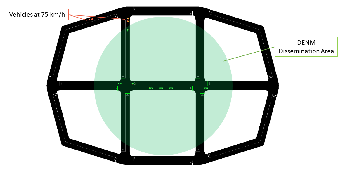
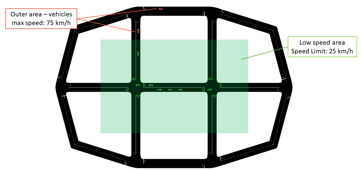
At a glance, in 802.11p vehicles broadcast periodic CAM messages and an RSU periodically broadcasts DENM messages to inform vehicles travelling in a low speed area to slow down. In this case CAMs and DENMs messages are encapsulated inside BTP and GeoNetworking. In LTE, instead, the CAM messages are forwarded to a remote host (behind an eNB + EPC), which analyzes the position of the vehicles and sends unicast DENMs to vehicles entering a low speed area to change their maximum allowed speed. In this case, due to the absence of a MBMS module in the LTE framework of ns-3, all the messages are sent in unicast. CAM and DENM messages are encapsulated inside BTP, GeoNetworking, UDP and IP.
802.11p application logic
The map is divided into two areas: a circular area in the middle of the map, with a radius of 90 m, on which DENMs are broadcasted by the RSU (with their GeoArea set accordingly), where the maximum speed is 25km/h and an outer area, where the speed limit is set to 75km/h.
The RSU disseminates a DENM every second in the area mentioned before, and continues its transmissions until it receives CAMs from vehicles in the map. When no CAMs are received for more than 5 seconds, the DENM dissemination in paused, until new vehicles enter the scenario and new CAMs are received by the RSU.
LTE application logic
The map is divided into two areas: the area in the middle, where the maximum speed is 25km/h and an outer area, where the speed limit is set to 75km/h. In this case, DENMs cannot be transmitted using merely BTP and GeoNetworking, but they have to rely on UDP and IPv4, since the server is located in a remote host behind the eNB and EPC. The server checks whenever a transition between the two areas is performed by a vehicle, and, when it happens, it sends it a unicast DENM message to tell it to slow-down (or to let it speed-up again).
Mobility Traces and Facilities Layer
The mobility trace is contained in the file ns-3-dev/src/automotive/example/sumo_files_v2i_map/cars.rou.xml.
This SUMO map embeds some re-routers allowing the vehicles to continuously move in the map.
The CAMs and DENMs dissemination logics are in the modules inside the automotive/Facilities folder while the application logic resides on (areaSpeedAdvisorClient80211p.cc/.h, areaSpeedAdvisorClientLTE.cc/.h) and (areaSpeedAdvisorServer80211p.cc/.h, areaSpeedAdvisorServerLTE.cc/.h) inside automotive/Applications.
The user IS NOT expected to modify the code inside the "Facilities", "BTP" and "GeoNet" folders, but rather to use the ETSI Facilities Layer methods inside the application.
Important
If using the LTE version in this very simple toy case, it is possible to connect at most 23 UEs to the enB (due to the LENA framework currently implemented features). You can avoid this problem by using the option --ns3::LteEnbRrc::SrsPeriodicity=[value]" where [value]=0, 2, 5, 10, 20, 40, 80, 160, 320. In this way you can add more UEs. Example: ./waf --run "v2i-areaSpeedAdvisory-lte --ns3::LteEnbRrc::SrsPeriodicity=160"
List of the most important options:
--realtime [bool] decide to run the simulation using the realtime scheduler or not--sim-time [double] simulation time--sumo-gui [bool] decide to show sumo-gui or not--server-aggregate-output [bool] if true, the server will print every second a report on the number of DENM sent and CAM received correctly--sumo-updates [double] frequency of SUMO updates--csv-log [string] prefix of the CSV log files where to save the disaggregated data coming from the CAMs received by the server and the DENMs received by the vehicles (the user can then use this sample application to build more complex logging mechanisms and/or log additional data coming from the server and/or the vehicles)
ms-van3t currently supports three stacks/communication technologies for V2V:
- 802.11p (sample program name:
v2v-emergencyVehicleAlert-80211p) - LTE-V2X Mode 4 (sample program name:
v2v-emergencyVehicleAlert-cv2x) - NR-V2X Mode 2 (sample program name:
v2v-emergencyVehicleAlert-nrv2x))
To run the program:
./ns3 run "v2v-emergencyVehicleAlert-cv2x" or
./ns3 run "v2v-emergencyVehicleAlert-80211p" or
./ns3 run "v2v-emergencyVehicleAlert-nrv2x"
- Nodes are created in the ns3 simulation as vehicle enters the SUMO simulation
- A full NR-V2X, LTE-V2X or 802.11p stack is implemented at lower layers
In this example, every vehicle that enters the scenario will start sending CAMs with a frequency between 1 Hz and 10 Hz (according to the ETSI standards). The vehicles are divided into "passenger" vehicles (i.e., normal vehicles) and "emergency" vehicles.
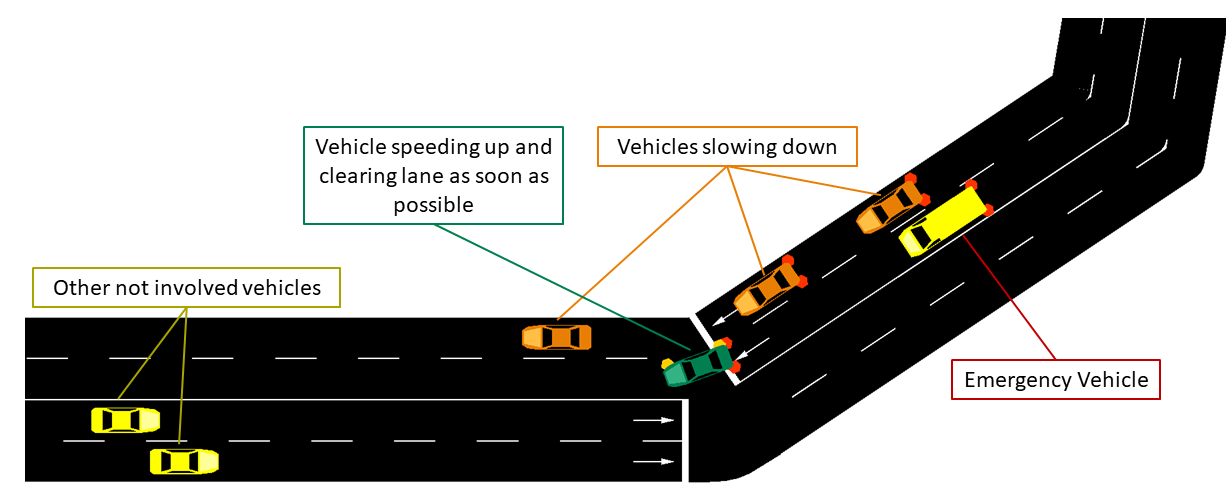
A CAM generated by an emergency vehicle will have the "StationType" Data Element (i.e. a field of the message) set to "specialVehicles". When normal vehicles receive these CAM messages from an emergency vehicle, they will check whether their heading is similar to the one of the emergency vehicle and which is their distance to the latter.
If the heading is similar and the distance is small enough, it means that the emergency vehicle is approaching. In this case, the receiving vehicles will either slow down (if on a different lane than the one the emergency vehicle is travelling on) or change lane as soon as possible (speeding up for a little while, if necessary, when they are on the same lane as the emergency vehicle).
When acting, in the SUMO GUI, vehicles will either turn orange (different lane --> slow down) or green (same lane --> clear path as soon as possible).
The CAMs and DENMs dissemination logic are in the modules inside the automotive/Facilities folder while the application logic is inside emergencyVehicleAlert.cc/.h (in automotive/Applications).
The user IS NOT expected to modify the code inside the "Facilities", "BTP" or "GeoNet" folders, but rather to use the ETSI Facilities Layer methods inside the application.
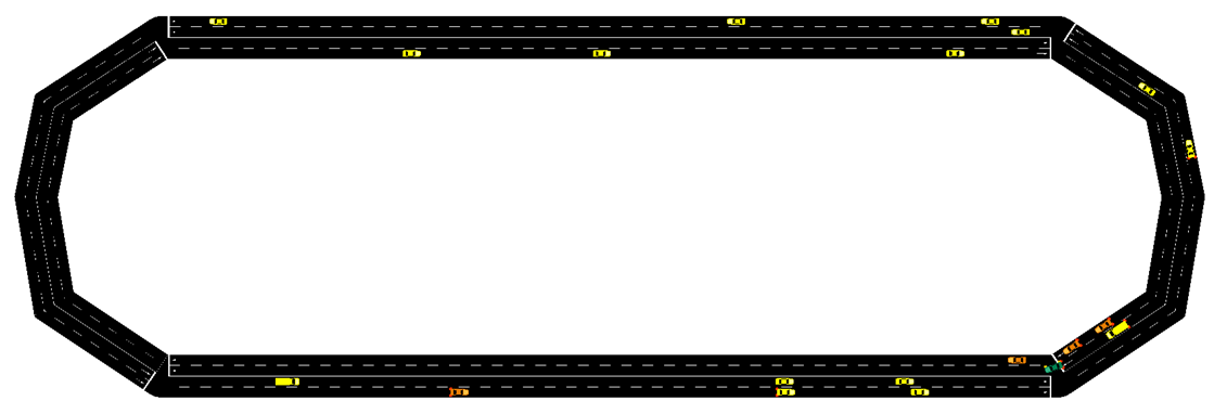
The SUMO scenario comprehends a ring-like topology, with two directions and two lanes for each direction (with a total of 4 lanes).
The mobility trace is contained inside the file automotive/example/sumo_files_v2v_map/cars.rou.xml.
The SUMO map also embeds some re-routers allowing the vehicles to continuously travel on the available road segments.
List of the most important options:
--realtime [bool] decide to run the simulation using the realtime scheduler or not--sim-time [double] simulation time--sumo-gui [bool] decide to show sumo-gui or not--sumo-updates [double] frequency of SUMO updates--csv-log: [string] prefix of the CSV log files where to save CAMs and DENMs disaggregated data and statistics
ms-van3t also includes an example of an emulation application, which is able to send the CAMs and DENMs generated by the vehicles, (virtually) travelling on the SUMO map, over a real network, by relying on a physical interface.
The same application should also be able to receive CAMs and DENMs coming from the external world (i.e. from a certain physical interface of the device running ns-3).
For the time being, this sample application is relying on the same map and mobility traces of the V2V application and it sends both CAM messages and periodic DENM messages, as an example on how both kinds of messages can be emulated and sent to the external world.
In order to properly work, the emulator application should always run in real time, and the device on which ns-3 is run should be able to handle the specified number of vehicles without delays and without slowing down.
As it is communicating with the external world, it handles only ASN.1 standard-compliant messages.
More in details, this application emulates N vehicles, each with its own CA and DEN basic service, and make them send the CAM/DENM messages and receive the CAM/DENM messages through a physical interface (specified with the "interface" option), instead of using any ns-3 simulated model. This should enable, in the future, hardware-in-the-loop testing and evaluation.
You can run it with:
./ns3 run "v2x-emulator --interface=<interface name>"
Where <interface name> is the name of the physical interface, on your PC, where CAMs will be sent.
Please note that the interface, in order to work with ns-3, should be put in promiscuous mode.
You can put an interface in promiscuous mode with:
sudo ip link set <interface name> promisc on
The promiscuous mode can then be disabled with:
sudo ip link set <interface name> promisc off
sudo may be needed to use the underlying ns-3 FdNetDevice: if you get a "permission denied" error, try adding --enable-sudo when doing ./ns3 configure and then running without sudo (ns3 will ask for your password if needed).
The logic of the application is contained inside model/Applications/v2x-helper.c/.h
UDP mode
In the default emulation mode, messages will be sent, through the specified interface, as broadcast packets encapsulated inside BTP and GeoNetworking.
The user can also specify, however, a UDP mode, enabling the transmission of messages to an external UDP server. In this case, the ETSI V2X messages (i.e. CAM, DENM) will be encapsulated inside BTP --> GeoNetworking --> UDP --> IPv4, and sent to a host with a specified IPv4 and port.
Any host is fine, but the following limitations apply:
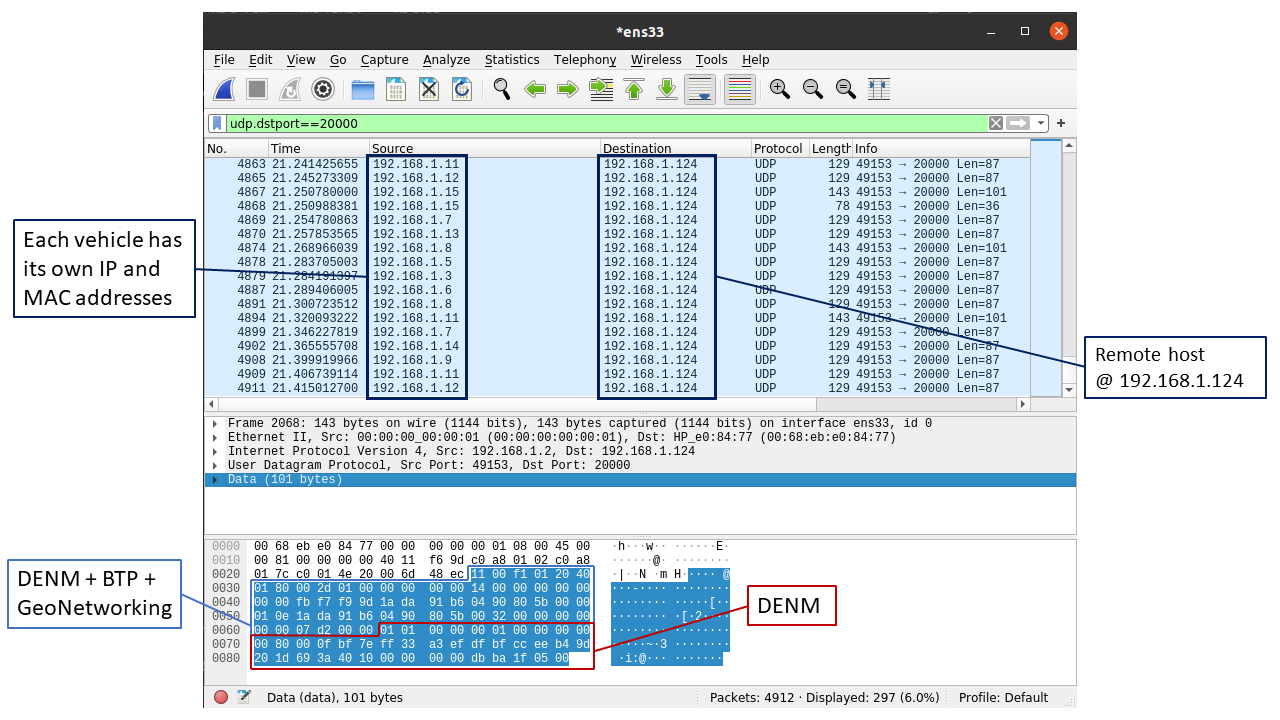
- The remote UDP server must be able to reply to the ARP requests sent by the vehicles, which will use their own source IP address and MAC and not the ones of the physical interface
- No loopback operations are possible so far, due to the limitation mentioned before
- The network at which the physical interface is connected shall be able to support the communication using spoofed MAC and IP addresses (otherwise, the ARP requests sent by ns-3 may not receive any reply). In general, we verified that any Ethernet link between ns-3 and the remote host receiving the UDP packets should be fine.
Screenshots
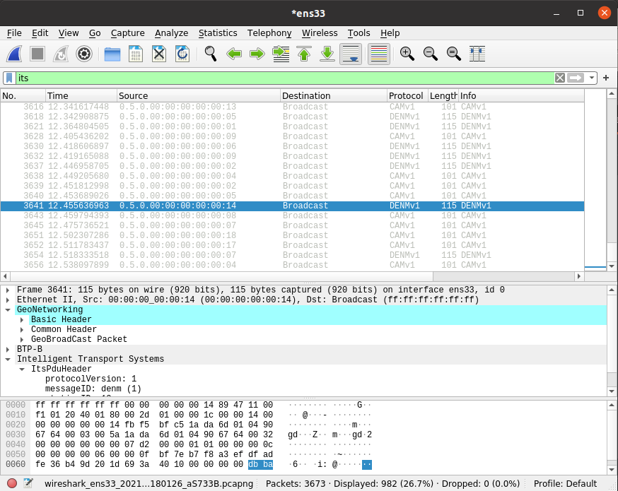
The following screenshot shows a Wireshark capture of the messages sent by the emulator application, when operating in normal mode and selecting the ens33 interface (e.g. ./ns3 run "v2x-emulator --interface=ens33")
The following screenshot shows a Wireshark capture of the messages sent by the emulator application, when operating in UDP mode, targeting a UDP server at 192.168.1.124/24, port 20000, and transmitting over the ens33 interface (e.g. ./ns3 run "v2x-emulator --udp=192.168.1.124:20000 --interface=ens33 netmask=255.255.255.0 gateway=192.168.1.1")
List of the most important options:
--sim-time [double] total emulation/simulation time--sumo-gui [bool] decide to show sumo-gui or not--sumo-updates [double] frequency of SUMO updates--send-cam [bool] enable vehicles to send CAMs--send-denm [bool] enable vehicles to send DENMs--interface [string] Name of the physical interface to send(/receive) V2X messages to(/from)--udp [string] To enable UDP mode and specify UDP port and IP address where the V2X messages are redirected (format: <IP>:<port>)--gateway [string] To specify the gateway at which the UDP/IP packets will be sent--subnet [string] To specify the subnet which will be used to assign the IP addresses of emulated nodes (the .1 address is automatically excluded)--netmask [string] To specify the netmask of the network
Requirement: if you want to use this module, Node.js should be installed (on Ubuntu/Debian you can install it with sudo apt install nodejs).
ms-van3t also comes with a web-based vehicle visualizer, able to display the vehicles travelling during the simulation on a map, rendered directly inside the user's browser.
It can be particularly useful when working with GPS Traces (see the gps-tc module), which are not
coupled with a GUI (as opposed to SUMO).
If you want to fully exploit its potentiality, you need a Mapbox token, as the visualizer relies on Mapbox to draw the street, hybrid and satellite map layers.
Once you get it, the mapbox token shall be copied inside the file mapbox_token in src/vehicle-visualizer/js
You can find more information on Mapbox here. They currently have quite good free tier options (allowing, at least in March 2021, up to 200000 free tile requests/month), which should be enough to use the ms-van3t vehicle visualizer without the need of paying anything. Please check them before signing up to Mapbox and getting a token to be used here. In general, we found out that a normal simulation, in which some sporadic zoom in/zoom out and three layer changes are performed, may require around 150/200 tile requests (we advise you to check often the tile request count on the Mapbox website, when you use your token).
In general, you should disable the vehicle visualizer when doing long batches of simulations.
If you do not own a Mapbox token (i.e. the mapbox_token file is empty), the visualizer will work in any case, with the following limitations:
- You must make an occasional use of the visualizer (i.e. no heavy usage allowed, no derivative apps can be developed starting from the visualizer). Not making an occasional usage will conflict with the Tile Usage Policy of OpenStreetMap, which is not considered acceptable. So, you must disable the vehicle-visualizer when doing batches of simulations to gather some results. You are responsible for this!
- Only one map layer (standard streets view from OpenStreetMap) will be available for use
In order to use the visualizer in your application, you need to add, in the main function (i.e. int main()),
the following code, which creates a new vehicleVisualizer object:
vehicleVisualizer vehicleVisObj;
Ptr<vehicleVisualizer> vehicleVis = &vehicleVisObj;
vehicleVis->startServer();
vehicleVis->connectToServer ();
Do not create a new vehicleVisualizer object with CreateObject or new, unless you plan to manually
call delete on it, as we rely on the object destructor in order to send a terminate message to the web visualizer
server and gracefully terminate it.
After creating a new vehicle visualizer object, you need to pass its pointer to the module which manages the vehicle's mobility. If you are using SUMO and TraCI, you can call:
sumoClient->SetAttribute ("VehicleVisualizer", PointerValue (vehicleVis));
Where sumoClient is a pointer to TraCI client object (Ptr<TraciClient>) you previously created.
If you are using, instead, GPS-tc, you can call:
GPSTCHelper.setVehicleVisualizer(vehicleVis);
Where GPSTCHelper is a GPSTraceClientHelper object. In this case, setVehicleVisualizer()
must be called before createTraceClientsFromCSV(), otherwise the vehicle visualizer
reference will not be passed to the GPS Trace Client objects managing the mobility of the
vehicles and no moving vehicles will appear on the map.
The vehicles displayed by the visualizer can also be inserted and updated from user applications (e.g. in an emulator application, you can use the CAMs received from the external world to add real vehicles to the map, together with the simulated ones).
In order to add and update a moving object from an application, the latter should have, first of all,
a reference to the visualizer object (i.e. Ptr<vehicleVisualizer>). Then, it will be able to use
<name of pointer to the vehicleVisualizer>->sendObjectUpdate() to add and update any object in the map.
In this case it is important to specify, as first argument of the sendObjectUpdate() function, an object ID which must be different from the IDs of the simulated
vehicles.
You can also refer to the examples inside src/automotive/examples, which all (but the V2X emulator) include the possibility
of using the web-based vehicle visualizer via the --vehicle-visualizer=true option.
The visualizer, once a simulation has been started, can be opened inside any browser, as long as the simulation is running, at localhost:8080 (if a different HTTP port is not specified with the setHTTPPort() method of the vehicleVisualizer object).
To acknowledge us in your publication(s) please refer to the following publication:
@article{ms-van3t-journal-2024,
	title = {ms-van3t: An integrated multi-stack framework for virtual validation of V2X communication and services},
	journal = {Computer Communications},
	volume = {217},
	pages = {70-86},
	year = {2024},
	issn = {0140-3664},
	doi = {https://doi.org/10.1016/j.comcom.2024.01.022},
	url = {https://www.sciencedirect.com/science/article/pii/S0140366424000227},
	author = {F. Raviglione and C.M. Risma Carletti and M. Malinverno and C. Casetti and C.F. Chiasserini},
	keywords = {Connected vehicles, V2X, Virtual validation, Hardware in the loop},
}
Our manuscript is open access and it is available here.

