| Name | Github |
|---|---|
| Mazen Hassan | mhassan20328 |
| Kareem Amr | KareemAmr12 |
| Omar Mohamed | OmarMoheyeldinMohamed |
| Ahmed Dardir | ahesham900 |
- The car should navigate to follow a path between two lines.
- The car should stop whenever it detects an object infront of it.
- The car should continue moving again when the object moves from its path.
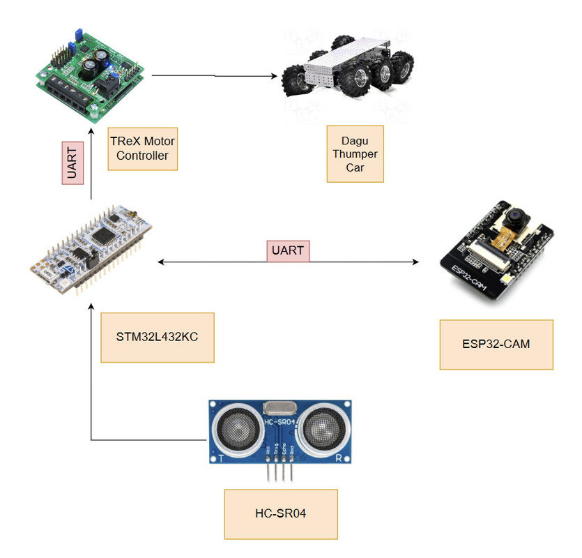
- For the STM32 Nucleo board: We decided to use STMCubeIDE for project management, source code editing, and program running.
- For the ESP32 CAM: We use Arduino IDE only to take a picture downsize it and send it to the STM32 Nucleo board.
| Component | Description | Image | Estimated Price |
|---|---|---|---|
| STM32L432KC Microcontroller | It is the main controller of the system. It receives the image from the ESP32 CAM and processes it to detect the lines. Also communicates with the ultrasonic sensor to detect objects infront of the car and stop it. | 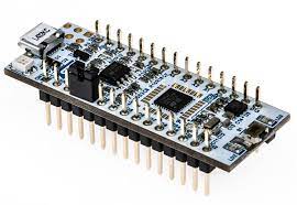 |
$11 |
| ESP32-Cam | It is the camera of the system. When prompted by the STM32 Nucleo board it takes a picture and sends it to the STM32 Nucleo board. |  |
$15 |
| Ultrasonic Sensor HC-SR04 | It is used to detect objects infront of the car and stop it. | 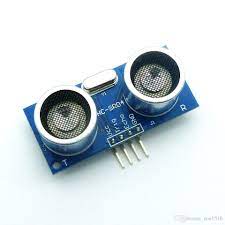 |
$2 |
| The Pololu TReX Motor Controller | It is used to control the motors of the car. | 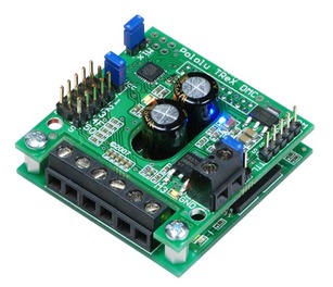 |
$200 |
| Dagu Wild Thumper 4WD Chassis | It is the car chassis. | 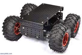 |
$350 |
| Jumper Wires | Used to connect the components together. |  |
$1 |
| Bread Board | Used to connect the components together. | 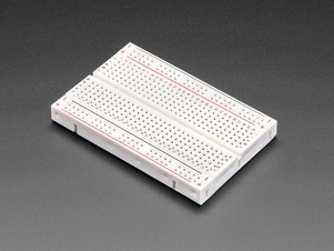 |
$2 |
- ESP32CameraSource folder contains all source files needed to program the ESP32 CAM.
- STMSource folder contains all source files needed to program the STM32 Nucleo board.
- Use the source code in the ESP32 CAM folder to program the ESP32 CAM.
- Open Arduino IDE and load the code into the camera. Note: you need to reset the camera anytime its power is cut off.
- Use the source code in the STM32 Nucleo board folder to program the STM32 Nucleo board. Note: you might want to use STMCubeMX to setup UART1 (setup baud rate at 19200), UART2 (setup baud rate to 230,400), and TIM1 (use a prescalar of 31 to achieve a 1us clock tick).
- Connect UART1 to the Pololu TReX Motor Controller.
- Connect UART2 to the ESP32 CAM.
- Connect the ultrasonic sensor trig and echo pins to PA3 and PA4 pins respectively on the STM32 Nucleo board.
The ESP32 CAM takes a picture when it receives a signal from the STM32 Nucleo board. The ESP32 CAM then downsizes the image and sends it to the STM32 Nucleo board using UART2. Below is an example of the image taken by the ESP32 CAM.
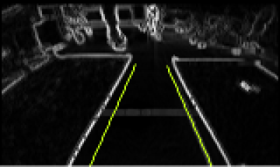
The STM32 Nucleo board receives the image from the ESP32 CAM and processes it to detect the lines using edge detection. An example of the image after edge detection is shown below.
A fisheye camera lens was used to capture a wider view of the road. This added a challenge to the lane detection algorithm as the two lane lines are not parrallel as seen in the image. Therefore the lane detection algorithm now simulates two lines that would have been the car tires' path and if these lines intersect the lane lines then the car should move in the opposite direction. For example, if the line from the left tire intersects a lane line the car should move to the right and vice versa. The image below shows the two lines simulated by the algorithm.
Link For Demo: Demo
- Try downsizing the image more to reduce the time needed to send the image.
- May want to use Radar instead of the ultrasonic sensor to detect objects infront of the car.
