This is the alpha version of a waveform viewer that can be coupled to the Treadle Firrtl Simulator.
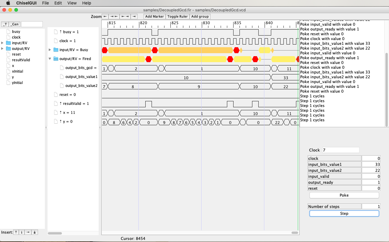
Here is a sample screenshot
- Automatic saving of state, including selected fields position in a VCD
- Compress time scale to just ready valid (/RV) fire events or valid /V valid events
- Just right click on a /RV or /V signal in selected signals panel
- Jump to Chisel source file from a signal
- Manual peek and poke top level IO ports and step the DUT
- Aggregate Ready/Valid and Valid IO bundles and show with color coded waveform state
- Construct arbitrary hierarchies in waveform viewer
- Automatically add driving signals to a user selected depth for a displayed signal
- Show the driving logic for any symbol in the DUT
At the shell problem use
cd $WORKDIR
git clone https://github.com/ucb-bar/chisel-gui
cd chisel-gui
sbt assembly
export PATH=$PATH:$WORKDIR/chisel-gui/utils/bin/
The simplest way to run is to have a related firrtl file and VCD file.
These can be generated by running unit tests of a DUT built in a project derived from
chisel-template.
See instruction for unit testers to generate VCD output.
This output along with the firrtl file (.fir suffix) are typically placed under the directory
test_run_dir, for example
test_run_dir/GCDTester/GCD.fir
test_run_dir/gcd.GCDTester/GCD.v
In your project dir, having installed chisel-gui as above, run
chiselgui test_run_dir/gcd.GCDTester/GCD.fir --vcd test_run_dir/gcd.GCDTester/GCD.v --chisel-source-paths src/main
For naming compatibility reasons, currently the VCD file you supply must be generated by the Treadle backend. We may be able to lift this restriction in the future.
For the full (and daunting) list of possible command line options run
chisel-gui --help
Most of those flags are not recommended for typical usage.
The application consists of 4 main panels.
- The Signal Selector Panel on far left
- The Selected Signal Panel comes next
- The WaveForm Panel comes after that. It and the Selected Signal Panel are linked together
- The InputControl Panel is on the far right.
The Signal Selector Panel and the InputControl Panel can be hidden manually. Also the Input Control Panel will not be shown if a Firrtl file is not specified
This is used to select signals for viewing in the wave form panel.
The panel allows limited filtering, _T_ and _GEN_ signal are filtered out
by default. There is a small text window that allows input of partial regular expressions.
When used only matching signal names will be shown.
At the bottom is a row of buttons that control where selected entries are placed in the selected signal panel.
All but the append to end button will not function if nothing is selected in the selected signal panel.
This is the signals that have been selected to have their waveforms viewed. The items in this can be re-arranged through dragging and dropping, which includes the building of arbitrary nested hierarchies. Groups can be created and items can be deleted by selecting and using the delete keys.
Most items have a pop-menu that provides, depending on context, the following choices
- DataFormat allows setting display radix
- Add Driving signals will add a list of signals that drive the clicked item
- Show Driving logic will show a nested display of the dut logic cone driving the clicked item
- Jump to source will attempt to open the source file associated with the clicked item
Caveats
Jump to Source is currently hard coded to try and open the Chisel .scala file in the IntelliJ idea in a OS-X environment. This operation should be command line configurable. Additionally a lot of the signals currently do not have references to their original source. This should be addressed in upcoming new versions of Chisel3 and Firrtl
This is pretty straightforward display of signal waveforms. An interesting feature is that ChiselGUI will attempt to aggregate (or roll-up) ready/valid and valid IO bundles. The ready/valid and valid signals will be displayed in a color coded form indicating the relative state of the flow control signals.
This panel allows the user to continue execution of the circuit. This panel presents a list of the top level IO ports. Values will be checked for format and legal range. Input Format allowed currently are
- 0xNNN or xNNN for hex
- bNNN for binary
- NNNN for decimal
where N is a digit appropriate for the radix. A minus sign can be placed at the front of any of the above if the input is an SInt.
Port values can be set then poked. Poking does not advance the clock, to do that you must
hit the step button.
Input fields can be populated from the input values under the cursor.
The input control panel keeps a history of any time a set of values is successfully poked. History will not add two entries adjacently that are the same, but non-adjacent duplicates can occur. There is an arbitrary limit of 50 entries in the history at the moment
All ports will be poked with the current visible values when the
pokebutton is hit. A blank field will not be poked, but is not an error
- Searching for events in VCD
- by one or more signals
- at multiple times (with specified relationships between times)
- More VCD manipulation
- Go back in time
- Input manipulation
- force arbitrary signals to a value