OS0-128 pointcloud rotated 180 deg
mnissov opened this issue · 12 comments
This has been discussed slightly in #84 but I figured the discussion has drawn out to the point where it deserves a a dedicated post with demonstration.
The problem is that the /points are not given correctly according to the coordinate frames from the software manual.
Bug
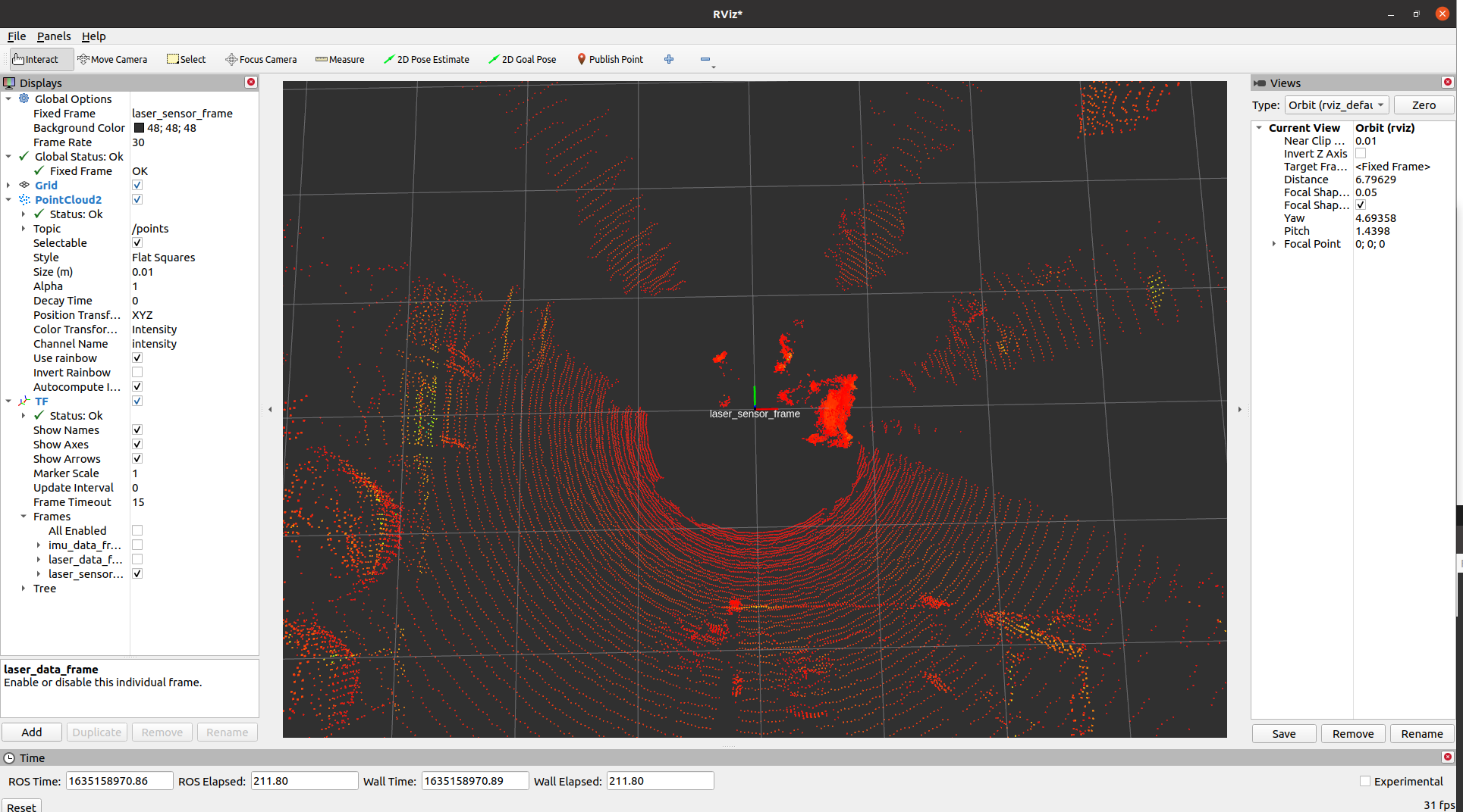
Case Setup: There are some objects in the background but, the object of interest will be me standing in front of the lidar on the connector side. According to the documentation this would mean I am standing on the positive x axis in lidar_frame and negative x axis in sensor_frame.
We can see the points are posted in lidar_frame by
$ ros2 topic echo /points --field header
stamp:
  sec: 5302
  nanosec: 2350300
frame_id: laser_data_frame
so the points are expressed in lidar_frame. Then, looking at the visualization in rviz one can see that I am placed oppositely to what one would expect. That is to say, in positive x axis in sensor_frame and negative x axis in lidar_frame despite standing in front of the connector.
Expectation
My expectation is that the point cloud would be rotated 180 deg about the z axis, such I am visualized standing along the positive x axis in lidar_frame and negative x axis in sensor_frame.
SW
I am running ubuntu 20.04 LTS, with ros galactic and the newest version of ros2_ouster_drivers installed by sudo apt install ros-galactic-ros2-ouster. The lidar is OS0-128 running version v2.1.1.
@mnissov What about the translations? Which translations should we use? as given in the software manual or in this driver which are 0, 0, 0 with respect to each other.
If you are rotating the laser_sensor_frame by 180 degrees then you also need to rotate imu_data_frame by 180 degrees.
I am attaching the pics of the imu linear acceleration data with its corresponding sensor alignment.
Z axis facing upwards:


X axis facing upwards:


Y axis facing upwards:


I am also displaying my URDF file for reference. Here the laser_sensor_frame is at the the same position(translation) as the sensor frame in the ouster manual just 180 degrees rotated.
parent link="laser_sensor_frame"
child link="laser_data_frame"
origin xyz="0.0 0.0 0.03618" rpy="0.0 0.0 3.141592653589793"
parent link="laser_sensor_frame"
child link="imu_data_frame"
origin xyz="0.006253 -0.011775 0.007645" rpy="0.0 0.0 3.141592653589793"
So i wasn't really intending on fixing the problem myself. This bug to me seems indicative of some error deeper in the driver and I was hoping this could lead to a solution.
But yes, you're right that if one were to make a basic solution then one would need to rotate both the laser and imu frames accordingly. Regarding translations, i just followed the recommendations from the software manual.
Ok thanks for your reply. Let's see what @SteveMacenski has to say in this.
Do you see this in ROS 1 using the ouster example repo? We use the same client code as them and wrapped in the new framework for ROS 2. If the issue is in parsing the pointcloud, then I suspect it lives in the client code, which would need to be changed there before we can accept a patch here. We strictly keep the client in ROS 2 the same as from Ouster itself so we can easily make drop-in replacement changes when Ouster pushes update to their client.
In ROS however, positive X axis should be forward, regardless of what Ouster's documentation says. That's the documentation for if you connect to the sensor what you get out of it, that is not related to any packages that get the data out and populate it into another ecosystem (like ROS) which have their own standard conventions to ensure drop-in replacability of sensors from many vendors. Though its hard for me to look at pictures without ground truth to tell if that's what's going on here or not. Either way, the perceived bug is probably in the client code when buffering data, which would be an Ouster Client issue, not a ROS 2 driver issue.
The ROS1 driver works as expected. Looking at sensor output from the ros1 and ros2 driver the two pointclouds are offset 180 degrees.
Regarding coordinate frames, I'm not quite sure what you mean by "regardless of what Ouster's documentation says". If the laser_data_frame coordinate frame in the ros2 driver doesn't correspond to the matching frame described in the documentation (positive x axis points towards connection, i.e. "backwards") then I've had a large misunderstanding.
I'll try and make the comparison more clear one of the following days.
Edit: Regarding the images, the only thing to see is me approaching the sensor. I know there is noise in the background and from the ground, but the only points was that I approached the sensor on the connector side. As has some expectation of how the pointcloud is represented with respect to the laser_sensor_frame and laser_data_frame, and that my expectation is the opposite of what is visible.
The ROS1 driver works as expected.
Huh, that is interesting then. They should be the same since they use the same buffering logic on the packets to build the pointclouds https://github.com/ros-drivers/ros2_ouster_drivers/blob/galactic/ros2_ouster/include/ros2_ouster/processors/pointcloud_processor.hpp#L90. Maybe its just TF is being submitted incorrectly rather than the data being in the wrong order? That would be an easy fix.
But again, it looks like we simply use what the client provides us from the sensor https://github.com/ros-drivers/ros2_ouster_drivers/blob/galactic/ros2_ouster/src/ouster_driver.cpp#L186
The +X should be forward on the laser frame by ROS conventions. If that is the same as Ouster docs, then A-OK on that. But if they are different, we follow ROS conventions for ROS drivers to make sure that sensors are all drop-in replaceable.
I looked into the transform as described in #84 an it seemed to be fine.
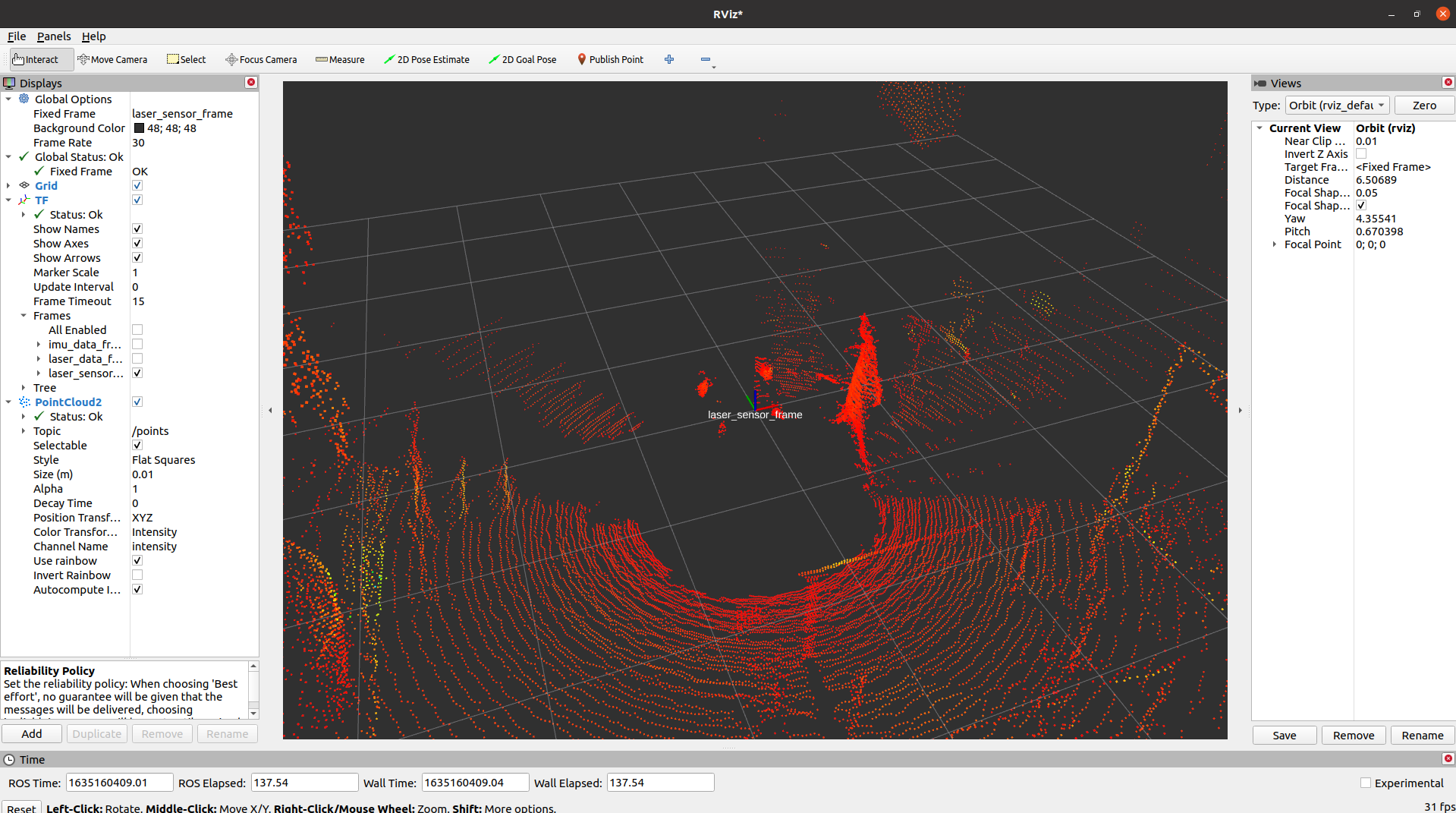
Also, looking at rviz using laser_data_frame as fixed frame shows the same type of problem: the 180 deg flip. I assume that shouldn't be effected by a bad transform.
Frames
My point with the frames is purely just that there are more than one in the Ouster, and they aren't all aligned. In the ros2 driver you have defined laser_sensor_frame and laser_data_frame, their x-axes are 180 deg offset, so obviously one cannot point forward.
I was just trying to relate the terminology in the driver to the manual such that my expectation regarding the visualization was justified, i.e. object near LIDAR cable connector -> positive x-axis in laser_data_frame.
The fix in #84 looks good to me. Sorry, I've also been on PTO so just catching up now.
Sorry for the misunderstanding. The fix in #84 only effects the translation and not the problem with the rotation. But the transforms published in that cpp file look to be matching to the software manual.
In an earlier message I said I would make a comparison between ros1/ros2 to highlight the problem, we no longer have this LIDAR so I won't be able to do that for the foreseeable future.
@SteveMacenski, we were able to source some ouster lidars again. So I'm returning with a demonstration of my aforementioned problem w/ ros1 and ros2 demos.
Sensor Frame Definition
Here is the sensor_frame definition from the software manual

I assume this should be what is referred to by sensor_frame in the ros2 driver parameters.
Physical Setup
This is the physical setup

So, one would expect to see the cardboard board in the positive x-axis of the sensor_frame, correct me if this is a misunderstanding.
ROS2
sensor_frame

laser_frame

ROS1
sensor_frame here called os_sensor

laser_frame here called os_lidar

Conclusion
ROS1 node seems to work as expected, ROS2 node seems to be missing something. In ros2 both laser_frame and sensor_frame are the opposite of what I would expect, perhaps there is a misnaming somewhere?
Appendix
ros2 config
/lidar/driver:
  ros__parameters:
    lidar_ip: 10.1.2.10
    computer_ip: 10.1.2.1
    lidar_mode: "512x10"
    imu_port: 7505
    lidar_port: 7504
    sensor_frame: lidar # laser_sensor_frame
    laser_frame: lidar/laser # laser_data_frame
    imu_frame: lidar/imu # imu_data_frame

    # if False, data are published with sensor data QoS. This is preferrable
    # for production but default QoS is needed for rosbag.
    # See: https://github.com/ros2/rosbag2/issues/125
    use_system_default_qos: False

    # Set the method used to timestamp measurements.
    # Valid modes are:
    #
    #   TIME_FROM_INTERNAL_OSC
    #   TIME_FROM_SYNC_PULSE_IN
    #   TIME_FROM_PTP_1588
    #   TIME_FROM_ROS_RECEPTION
    #
    # (See this project's README and/or the Ouster Software Guide for more
    # information).
    #
    timestamp_mode: TIME_FROM_INTERNAL_OSC

    # Mask-like-string used to define the data processors that should be
    # activated upon startup of the driver. This will determine the topics
    # that are available for client applications to consume. The defacto
    # reference for these values are defined in:
    # `include/ros2_ouster/processors/processor_factories.hpp`
    #
    # For convenience, the available data processors are:
    #
    # IMG   - Provides 8-bit image topics suitable for ML applications encoding
    #         the range, ambient and intensity data from a scan
    # PCL   - Provides a point cloud encoding of a LiDAR scan
    # IMU   - Provides a data stream from the LiDARs integral IMU
    # SCAN  - Provides a synthesized 2D LaserScan from the 3D LiDAR data
    #
    # To construct a valid string for this parameter join the tokens from above
    # (in any combination) with the pipe character. For example, valid strings
    # include (but are not limited to):
    #
    # IMG|PCL
    # IMG|PCL|IMU|SCAN
    # PCL
    #
    proc_mask: IMG|PCL|IMU|SCAN
ros1 launch
<launch>

  <arg name="sensor_hostname" default="10.1.2.10" doc="hostname or IP in dotted decimal form of the sensor"/>
  <arg name="udp_dest" default="10.1.2.1" doc="hostname or IP where the sensor will send data packets"/>
  <arg name="lidar_port" default="7504" doc="port to which the sensor should send lidar data"/>
  <arg name="imu_port" default="7505" doc="port to which the sensor should send imu data"/>
  <arg name="replay" default="false" doc="do not connect to a sensor; expect /os_node/{lidar,imu}_packets from replay"/>
  <arg name="lidar_mode" default="512x10" doc="resolution and rate: either 512x10, 512x20, 1024x10, 1024x20, or 2048x10"/>
  <arg name="timestamp_mode" default="" doc="method used to timestamp measurements: TIME_FROM_INTERNAL_OSC, TIME_FROM_SYNC_PULSE_IN, TIME_FROM_PTP_1588"/>
  <arg name="metadata" default="meta.json" doc="path to read or write metadata file when replaying or receiving sensor data, respectively"/>
  <arg name="viz" default="true" doc="whether to run a rviz"/>
  <arg name="rviz_config" default="-d $(find ouster_ros)/viz.rviz" doc="optional rviz config file"/>
  <arg name="tf_prefix" default="" doc="namespace for tf transforms"/>
  <arg name="udp_profile_lidar" default="" doc="lidar packet profile: LEGACY, RNG19_RFL8_SIG16_NIR16_DUAL"/>

  <node pkg="ouster_ros" name="os_node" type="os_node" output="screen" required="true">
    <param name="~/lidar_mode" type="string" value="$(arg lidar_mode)"/>
    <param name="~/timestamp_mode" type="string" value="$(arg timestamp_mode)"/>
    <param name="~/replay" value="$(arg replay)"/>
    <param name="~/sensor_hostname" value="$(arg sensor_hostname)"/>
    <param name="~/udp_dest" value="$(arg udp_dest)"/>
    <param name="~/lidar_port" value="$(arg lidar_port)"/>
    <param name="~/imu_port" value="$(arg imu_port)"/>
    <param name="~/metadata" value="$(arg metadata)"/>
    <param name="~/udp_profile_lidar" value="$(arg udp_profile_lidar)"/>
  </node>

  <node pkg="ouster_ros" type="os_cloud_node" name="os_cloud_node" output="screen" required="true">
    <remap from="~/os_config" to="/os_node/os_config"/>
    <remap from="~/lidar_packets" to="/os_node/lidar_packets"/>
    <remap from="~/imu_packets" to="/os_node/imu_packets"/>
    <param name="~/tf_prefix" value="$(arg tf_prefix)"/>
  </node>

  <node if="$(arg viz)" pkg="rviz" name="rviz" type="rviz" args="$(arg rviz_config)" output="screen" required="true" />
  <node if="$(arg viz)" pkg="ouster_ros" name="img_node" type="img_node" output="screen" required="true">
    <remap from="~/os_config" to="/os_node/os_config"/>
    <remap from="~/points" to="/os_cloud_node/points"/>
    <remap from="~/points2" to="/os_cloud_node/points2"/>
  </node>

  <!-- for compatibility with < 1.13 rosbags -->
  <node pkg="topic_tools" name="relay_lidar" type="relay" args="/os1_node/lidar_packets /os_node/lidar_packets" />
  <node pkg="topic_tools" name="relay_imu" type="relay" args="/os1_node/imu_packets /os_node/imu_packets" />

</launch>